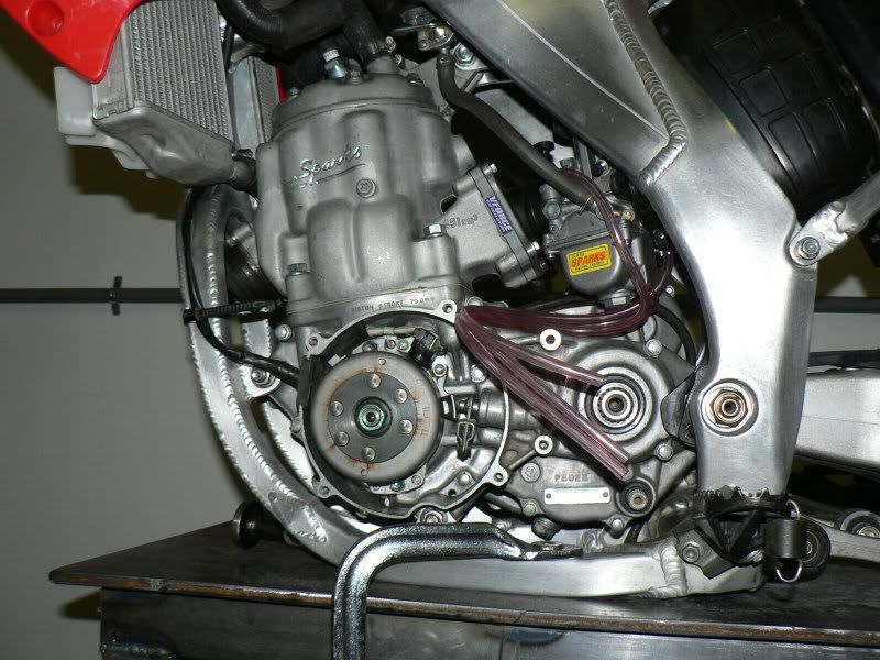
Another 03 crf450 Conversion

Building Tips, Suspension Set Ups, Conversion Parts .... Build to your Heart's Content!
KE 336
Posts: 223
Joined: May 9th, 2008, 8:14 pm
Last active:
Location: FT. Worth,TX

Another 03 crf450 Conversion

Post by KE 336 »

Here's a few of mine. I know lots of these photos are redundant but, keep in mind the new guy thinking of starting a build can never gety enough pictures.
I cut the frame tubes 1/2" above the nutserts on the side.
Image

Then removed the old coil mounts.
Image

Then used my nig-gyver jack to see how far I could open the frame and still have it close up. I'm short on time at the moment so explain this detail when I post again.
Image
User avatar
AlisoBob
"Hoon-father"
Posts: 15404
Joined: May 31st, 2007, 6:39 pm
Last active:
Location: Aliso Viejo Ca

Re: Another 03 crf450 Conversion

Post by AlisoBob »

KE 336 wrote: Then used my nig-gyver jack ....
I'm pleased to see that you using the correct vernacular......

:flip:
KE 336
Posts: 223
Joined: May 9th, 2008, 8:14 pm
Last active:
Location: FT. Worth,TX

Post by KE 336 »

Yeah Bob, ya gotta call it like it is. Anyway, I didn't want to cut windows in the cradle tubes to get the extensions in and I also didn't want just butt welds holding it together so I was testing to see how much plug I could squeeze in.

Next step was to cut the bottom tab of the lower left radiator mount. The top of the Y will end up in that area when raised on the downtube.
Image

Then cut the Y off just above the welds.
Image

Cut, picked and pulled left over downtube from inside the Y and cleaned it up. You can see in the first one, the down tube doesn't fit too far into the Y and the second shows how the Y tapers inward so you can't push it very far up on the downtube anyway.
Image
Image

I refit the Y back on the downtube just to see how much space it made.
Gained about 7/8" before cutting anymore of the downtube.
Image
Image
KE 336
Posts: 223
Joined: May 9th, 2008, 8:14 pm
Last active:
Location: FT. Worth,TX

Post by KE 336 »

I started cutting the down tube to raise the Y. First cut was about 2" above the weld cut of the Y.
Image

After that, the problem comes getting the Y to line up with the cradle tubes. The downtube starts getting thicker in the back and the Y tapers inward. This makes the Y want to kick forward. Took lots of little cuts and fitting to get it to line up. It takes a hammer and wood block to get it lined up good.
Image
Image
Image
Image
Image
User avatar
Hellbear
Posts: 2255
Joined: June 13th, 2007, 8:14 pm
Last active:
Location: Richmond Hill, GA

Post by Hellbear »

Nice! :cool:
Image
KE 336
Posts: 223
Joined: May 9th, 2008, 8:14 pm
Last active:
Location: FT. Worth,TX

Post by KE 336 »

Heres a few more. I needed to add 3" to the cradle and the 02-04-5?
Has the rectangle tube. It also isn't real consistent on size either. One side measures .775 x 1.200 and the other side is .785 x 1.190. I bought oversize solid and milled to match tubing. Cut to 4" total length. I split the difference in size and made the extentions .780 X 1.195.
Image
I drilled two small holes thru each one and milled the ends 1/2" back from each end to fit inside the tube. Just like the O.D. of the tube, the walls vary so I just got close to size with the mill then hand filed so the stubs would fit tight in the tubes. One on right has been filed some, left is straight off the mill.
Image
User avatar
zorak-2
Posts: 279
Joined: June 17th, 2007, 4:21 am
Last active:
Location: clovis,ca

Post by zorak-2 »

KE 336 wrote:I drilled two small holes thru each one and milled the ends 1/2" back from each end to fit inside the tube. Just like the O.D. of the tube, the walls vary so I just got close to size with the mill then hand filed so the stubs would fit tight in the tubes. One on right has been filed some, left is straight off the mill.
Image
What are the holes for?

pm sent
This site rocks
GEN 4 CRF500
User avatar
eyesky2002
Posts: 492
Joined: October 30th, 2007, 8:31 am
Last active:
Location: SW Iowa
Contact:

Post by eyesky2002 »

NICE :cool:
"When your riding your living... Everything else is just waiting!"

MXMotoworx.com
2003 Honda CR500AF
User avatar
Roostius_Maximus
Site Admin
Posts: 4641
Joined: November 16th, 2007, 3:24 pm
Last active:
Location: Mt Nebo, Manitoba, Canada
Contact:

Post by Roostius_Maximus »

The holes represent center if the material was square dimension of its narrowest part, he's likely going to reference from that to round the corners off
User avatar
dannygraves
Posts: 8020
Joined: June 1st, 2007, 2:03 pm
Last active:
Location: Las Vegas, NV

Post by dannygraves »

:cool:
'09 kx450f 4-Poke
Gen-4 trail bike --SOLD--
Gen-3 badass trail/mx bike --SOLD--
Gen-1 built dunes bike --SOLD--
'05 klx110 --SOLD--
'95 pw80
Image
KE 336
Posts: 223
Joined: May 9th, 2008, 8:14 pm
Last active:
Location: FT. Worth,TX

Post by KE 336 »

Roostius_Maximus wrote:The holes represent center if the material was square dimension of its narrowest part, he's likely going to reference from that to round the corners off
Roostius, WTF, that sounds like machinist talk. :lol: I'm far from being one of those. I can operate a lathe and mill to do simple shit, but thats about it. I put the holes in there so it wouldn't be completly solid AND IF
I heat treat it, it will act as a gas passage. Other wise I would have to drill relief holes in the tubes on both sides of the extensions. I'm still undecided on that process for now though. You can't really get a true center on the tube because the wall thickness varies from .100-.135 so you have to measure each side individually to see how much to take off each side.I just used a file to round the corners.
eyesky, I got to publicly thank you for the build you put out there. You can't imagine how much time I spent studying your work! :applaud:
BTW, I've been thinking and thinking on something different for the headstay and a lightbulb finally went off last night. Can't wait to get to that point to see if it works. Won't be near as nice as TTMs billet but should be plenty strong and easy enough for any home builder to do.
Going to try and post a few more pics today if I get time.
User avatar
Roostius_Maximus
Site Admin
Posts: 4641
Joined: November 16th, 2007, 3:24 pm
Last active:
Location: Mt Nebo, Manitoba, Canada
Contact:

Post by Roostius_Maximus »

:lol:
KE 336
Posts: 223
Joined: May 9th, 2008, 8:14 pm
Last active:
Location: FT. Worth,TX

Post by KE 336 »

Okay, Here's some more. This one just shows the fit. That is as far as they go in without being tapped with a hammer on wood block.
Image
This one just shows they are tight and not falling out. Almost forgot,
I drilled a hole in each tube to get a little weld on each of the four plugs
which you'll see in some of the next photos.
Image
Image
Time for the high tech jack again. I angled the Y up on the downtube and just opening the frame. Wish I could have took more pictures of this but I was kind of busy. I did have to tap the bottom of the frame tubes with wood while I was releasing the jack. The natural force of the frame squeezed it all together.
Image
Look Ma...no welds! This is the part I couldn't have been more pleased with. It is solid as hell without any welds at all and the alignment is near perfect. Its kind of hard to tell but in these, the frame is suspended in air from a strap. This was just to show how tight it is without even being welded yet.
Image
Image
I'm going to take the donor bike for one more ride this weekend. If it comes home Sunday evening still running good, the motor will be coming out shortly after. Hopefully next week.
Last edited by KE 336 on April 23rd, 2009, 9:17 pm, edited 1 time in total.
User avatar
NightBiker07
Posts: 1942
Joined: April 16th, 2008, 8:59 pm
Last active:
Location: USA

Post by NightBiker07 »

i wish i still had access to this kind of equipment......it would make these projects SO much easier. The things i used to make in high-school for simple home repairs for stuff you simply couldnt get parts for was absolutely ridiculous!
2000 CR250, pipe, filter, Vforce

1980 XL80s
1969 Broncco TX-6

Natural selection favors Smart people, so nature selects morons to be slow and dumb for tigers and stuff too eat. But in our modern world there just aren't enough tigers.
ktm 620
Posts: 74
Joined: December 11th, 2008, 6:16 pm
Last active:
Location: wales uk

nice job mate

Post by ktm 620 »

nice job mate im going to do somthink thery simular in fact just the same has you have done with the y ecxtentions i do not athe axces to any laves or machenary like that but thers plenty othe enginears wear i live so shouildant be dificalt to get done im going to take the frame and aliy rounde a few today and excplayne wat i want done and will go frome ther good luck mate
KE 336
Posts: 223
Joined: May 9th, 2008, 8:14 pm
Last active:
Location: FT. Worth,TX

Post by KE 336 »

Yeah, having a machine to do the work makes things a lot easier but, I haven't done anything yet that couldn't be done with a hand saw and file.
Just takes much more time and effort. Also, If you have a drill press, you can buy a cheap 2 axis manual mill table to put on it for under $200. Not the best in the world but it would work just fine cutting aluminum.
oggo69
Posts: 259
Joined: November 6th, 2008, 5:48 am
Last active:
Location: Dublin , Ireland

Post by oggo69 »

good work dude .... keep it up :cool:
nmdesertrider
Posts: 678
Joined: February 22nd, 2008, 8:18 pm
Last active:

Post by nmdesertrider »

Nice build and nice pics- wish I had this thread when I did mine it would have saved me a lot of time.
03 CRF450/85 500
KE 336
Posts: 223
Joined: May 9th, 2008, 8:14 pm
Last active:
Location: FT. Worth,TX

Post by KE 336 »

Got the lower mounts done. Used .750x2"x2.5" 6061. Use a 13/32 drill bit for the holes. It's about as close to the original bolt hole size you can get. The taper works out to about 6degrees. The mill I use wasn't available when I shaped around the bolt holes so I did that by hand. I'll try and clean up on the machine before welding in place.
Image

I had to grind a little room for the bottom case bolt just below the clutch.

Image
Image
Image
KE 336
Posts: 223
Joined: May 9th, 2008, 8:14 pm
Last active:
Location: FT. Worth,TX

Post by KE 336 »

Left front mount fitted. The angle is roughly 5.5deg., notice the taper. This started off the same as lower mounts. You can also see my choice on location to cut the frame tube. I wanted the front mounts to act as a scab to reinforce that joint. Yellow line just shows rough shape it will be.
Image
Image
User avatar
zorak-2
Posts: 279
Joined: June 17th, 2007, 4:21 am
Last active:
Location: clovis,ca

Post by zorak-2 »

i am giong to do the same thing with mine and I am also giong to put peice on the upper part of the leg and also on the y section.Stronger is better in opinion its not worth get mhurt if is was to break at 60mph.

Looks awesome
This site rocks
GEN 4 CRF500
KE 336
Posts: 223
Joined: May 9th, 2008, 8:14 pm
Last active:
Location: FT. Worth,TX

Post by KE 336 »

zorak-2 wrote:i am giong to do the same thing with mine and I am also giong to put peice on the upper part of the leg and also on the y section.Stronger is better in opinion its not worth get mhurt if is was to break at 60mph.

Looks awesome
Yes, after seeing the broken bike photo, I thought the same thing. Planning to put a scab in area shown and also on the back side of it.
Image
User avatar
zorak-2
Posts: 279
Joined: June 17th, 2007, 4:21 am
Last active:
Location: clovis,ca

Post by zorak-2 »

KE 336 wrote:
zorak-2 wrote:i am giong to do the same thing with mine and I am also giong to put peice on the upper part of the leg and also on the y section.Stronger is better in opinion its not worth get mhurt if is was to break at 60mph.

Looks awesome
Yes, after seeing the broken bike photo, I thought the same thing. Planning to put a scab in area shown and also on the back side of it.
Image
X2 that is my plan also :wink:
This site rocks
GEN 4 CRF500
User avatar
Exnav
Posts: 1420
Joined: November 4th, 2007, 8:42 pm
Last active:
Location: St. Louis, Missouri

Post by Exnav »

Check out Chachi's work.
Image
Image
Money ain't got no owners, only spenders - Omar Little
KE 336
Posts: 223
Joined: May 9th, 2008, 8:14 pm
Last active:
Location: FT. Worth,TX

Post by KE 336 »

Got a little more done. Fitting the pipe it was jacked way too far up in the back.
Image
I put some heat in the bend and took some of the angle out.
Image
Got it to fit better then made a bracket. It uses the 450 muffler mount hole and fender mount hole. Just need to clean up the mount. Used a sawsall and hand drill to make.
Image

Image
Post Reply