I am in the process of freshening up my 2001 SH CR 500 AF.
I hope to cover the following subjects in future posts.
• Engine refresh
• Gen 3 body on Gen 2 chassis mod
• Using the twin spar frame as additional fuel storage
'01 AF "refresh"

Re: '01 AF "refresh"
maddog1927 wrote: • Using the twin spar frame as additional fuel storage
Can't wait!!!
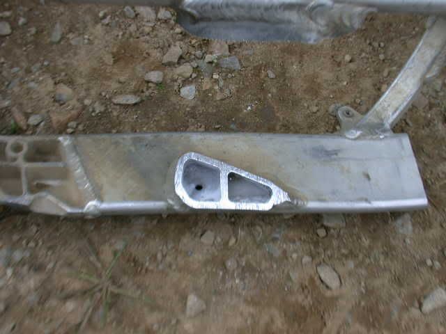
The Gen 2 spars are open to the steering tube.
I have my Gen 3 plumbed, including the downtube and the oval stiffeners that tie the spars to the front downtube. All in all it holds just under 1/2 gallon. I ended up with some pinhole leaks, so haven't been using the frame for storage for a while. Also, a couple of the the areas I thought were open weren't... I have to drill through to the different chambers to open them up. When I do an engine-out refresh on my bike I'll do the drilling and weld up the pinholes at the same time.
Tying all the "reservoirs" together, adding a shutoff and in-line fuel filter makes for a spaghetti mess of fuel lines.
-
maddog1927

- Posts: 313
- Joined: April 4th, 2010, 8:10 am
- Location: Mesa, AZ
• Using the twin spar frame as additional fuel storage
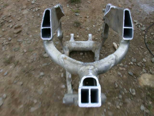
Looks like that is a little more complicated than I thought. I read a post years ago on the other site and it seemed pretty simple, but looks like mikie1 is correct, the Gen 2 spars are open to the steering tube. I pressurized my frame tubes and the pressure bleed down, I could hear it coming out the steering tube.
I assume it looks like this picture of a Gen 3 125, which begs the question, how did mikie1 take care of that?
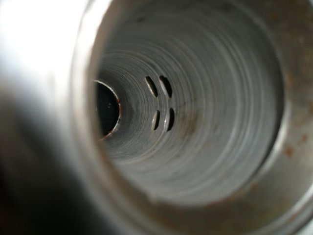
I still think it is a cool idea, but short of welding up the holes in the steering tube, which if possible would be a PITA, I don’t see how it could be properly done.
Looks like that is a little more complicated than I thought. I read a post years ago on the other site and it seemed pretty simple, but looks like mikie1 is correct, the Gen 2 spars are open to the steering tube. I pressurized my frame tubes and the pressure bleed down, I could hear it coming out the steering tube.
I assume it looks like this picture of a Gen 3 125, which begs the question, how did mikie1 take care of that?
I still think it is a cool idea, but short of welding up the holes in the steering tube, which if possible would be a PITA, I don’t see how it could be properly done.
I've just plugged them with some metal epoxy. There's a zillion types around.
We then used some Kreem tank sealant in the tubes used for the fuel cells - there are, once again, a lot of other fuel intended sealants around. There's many areas that may have a chance to have leaks appear, and you'd potentially spend a lot of time chasing them with a welder, and quite a few may not be accessible with a welder.
As for the plumbing - we used stainless right angle grease nipples, with the tip ground down to eject the check ball and spring, drilled and tapped thread in the frame, then as an extra precaution, metal epoxy neatly built up around the hex, on those that were in thin alloy. The grease nipple gave a very low profile - there may be other things you might find, but so far that's been the lowest profile outlets I've found.
Then use fuel approved line - small sized, to link the reservoirs together.
Using the frame helps with one of the things I don't like about AFs - the fuel being carried so bloody high.
I didn't do a Gen 2- Mine is a Gen 3 (2002 CR250). The Gen 3 250 spars butt into the steering tube-- the steering tube is solid. The Gen 2 steering tubes are cut out for the spars to fit into, then welded on.
Are you sure that picture is of a Gen 3? If so, the 125's are different from the 250's (and 450s). I plumbed my 450 frame back in '02. Good call on the grease nipples... I used brass fittings made for a gas-powered Remote Control buggy. I used JB weld on the fittings sort of like plumbers putty. No leaks at the fittings, but several pinholes elsewhere. I'll try the kream sealer next time- great suggestion.
Are you sure that picture is of a Gen 3? If so, the 125's are different from the 250's (and 450s). I plumbed my 450 frame back in '02. Good call on the grease nipples... I used brass fittings made for a gas-powered Remote Control buggy. I used JB weld on the fittings sort of like plumbers putty. No leaks at the fittings, but several pinholes elsewhere. I'll try the kream sealer next time- great suggestion.
-
maddog1927
- Posts: 313
- Joined: April 4th, 2010, 8:10 am
- Location: Mesa, AZ
-
maddog1927
- Posts: 313
- Joined: April 4th, 2010, 8:10 am
- Location: Mesa, AZ
-
maddog1927
- Posts: 313
- Joined: April 4th, 2010, 8:10 am
- Location: Mesa, AZ
I hacked a gen 2 250 into pieces after mainerAF on the other site had a thread about doing his gen 2 with fuel in the frame.
I took pics of all the pieces for this type of work if you need em I can post em.
He never said anything about stem problems but yes they are open. He did complain quite a bit about the junk coming out of the frame and plugging filters repeatedly. I have his phone #. He doesn't run it in the frame anymore due to the filter issue.
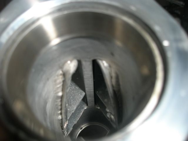
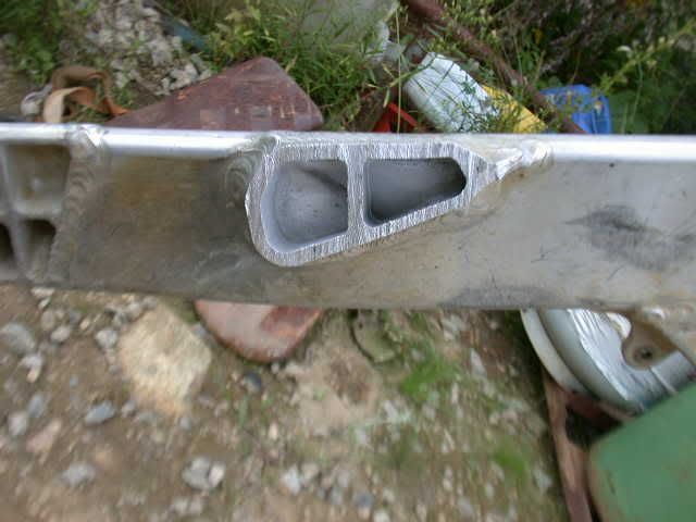
.maddog1927 wrote:bearosos have you ever done your epoxy method on a gen 2 250 like the 2nd picture?
The only generation AF I've never done is a Gen2 - weird but that's how it has gone.
But that looks far from impossible. Think laterally.
Consider a simple alloy plate, perhaps with a definite bend point, with the bend centre at the central, thick spine seen in that picture. A few of the horizontal sections of the spars are uneven in their penetration into the steering head, so, you could either file them so they all present an even, inner edge that would accommodate the 2 flat sections of the bent plate, to seal the spars at their faces. Or file/dremel/whatever, the spar faces back to the curved ID of the steering head to enable you to put in a curved piece of alloy -much neater, but more work of course - perhaps from your favourite beverage that comes in a can?
Either way will allow you to seal of the steering head, and get the clamps in and out with no drama.
Then use whatever metal epoxy that you prefer - I use the type that cures to be basically metal - machinable, file able, polish able etc, etc, etc.
Spend some time flushing out the frame tubes before you seal the steering head, other sections, and you won't have the problems of debris in the frame clogging lines / filters etc. That potential problem is also stopped dead by the lining of the frame with fuel intended sealant, it gets the bits that are obstinate about coming out in the flushing process. Just remember to do All welding before you seal things - including the cosmetic fixes of plastic grooves in the spars etc.
That is precisely why I used Kreem, I'd used it many times over the years and knew exactly how it worked and set. It applies thin and you make a maximum effort to keep the frame moving whilst you first apply it. I made a giro type holder so I could rotate it on all axis whilst using it. Other sealants you need to be wary of - you need to be aware of how thick / the viscosity of them before you use it. It takes a lot to clog a 3.175mm or 4.765mm hole with use of the correct sealant. And both those size holes present no problem whatsover with fuel flow / transfer.seanmx57 wrote:The holes that connect the spars to the crossmember where the head stay and the bend tubing above the head are not big and could clog with the creme sealant or at least cut way donw on flow. I'll measure them, memory says they are between 1/8" and 3/16"
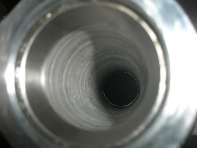
Im looking at the steering stem & I'm thinking why couldnt you drive out the bearing races & press in a pipe turned to that inner diameter, just thin wall pipe so it isnt an issue with the steering stem. The sealer would take care of the remainder of leakage. On the gen2 2001 250 you could do the same just clean it up with a carbide bit before hand so its flush or a little less. The gen 2 opening looks like it would make cleaning it out before hand easier too. Let me know if I'm up in the night here on my thinking. I'm quite interested in this though as the last conversion I did would go dry in 1hr & 45 min. Ran out of fuel 3 times. I gotta do something different on this next build.
Also are there holes into the flat oval piece of frame that connects from the spars to the upper part of the Y on that gen 2 frame?
Also are there holes into the flat oval piece of frame that connects from the spars to the upper part of the Y on that gen 2 frame?
-
Roostius_Maximus

- Site Admin
- Posts: 4641
- Joined: November 16th, 2007, 3:24 pm
- Location: Mt Nebo, Manitoba, Canada
- Contact:
just sleeve it. get on the lathe and make a sleeve out of aluminum and press it in, or jb it in there
http://www.youtube.com/user/500bigbore
My CR500 Tech Reference... http://sdrv.ms/1a0CIiz
MRE Components... http://sdrv.ms/1bs2zhd

My CR500 Tech Reference... http://sdrv.ms/1a0CIiz
MRE Components... http://sdrv.ms/1bs2zhd
-
maddog1927
- Posts: 313
- Joined: April 4th, 2010, 8:10 am
- Location: Mesa, AZ

Fk........ just shove a pop bottle full of mixed up fuel behind the number plate. 
Yah, I'm from Saskatchetoon!
MRE 02 250/500 conversion, pulse injector, twirp porting, coolhead, MRE ignition, blah blah blah blah... www.millarengines.com
MRE 02 250/500 conversion, pulse injector, twirp porting, coolhead, MRE ignition, blah blah blah blah... www.millarengines.com
-
maddog1927
- Posts: 313
- Joined: April 4th, 2010, 8:10 am
- Location: Mesa, AZ
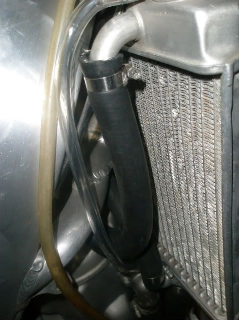
The front brake hose was starting to look a little tired, the potions with clear plastic had yellowed. I went to Fry’s Electronics and got a 36" section of ½" (1/4" recovered) heat shrink for about $3. It was tight getting over the fitting at the end of the hose. A little spray silicone helped. I used a heat gun (vs. my trusty lighter) starting at the master cylinder, working my way down.
I also installed some aftermarket fork guards. This is one of the few areas I prefer aftermarket over OEM. The oems on their best day are a funky milky white, then they yellow from there. Aftermarkets are crisp white. I installed Polisport brand. The fit was as you may have guessed not quite perfect. I had to drill/file out the mounting holes where the step bolts go. I filed some of the holes ex centrical to get them to fork protectors to move out away from the fork the way I wanted. I presume another aftermarket brand may have a better fit, or another OEM (yami/Suz/Kawi) may have a pure white that fits. The ‘01 SH os on the left, on the right is a low hr ‘02 250.
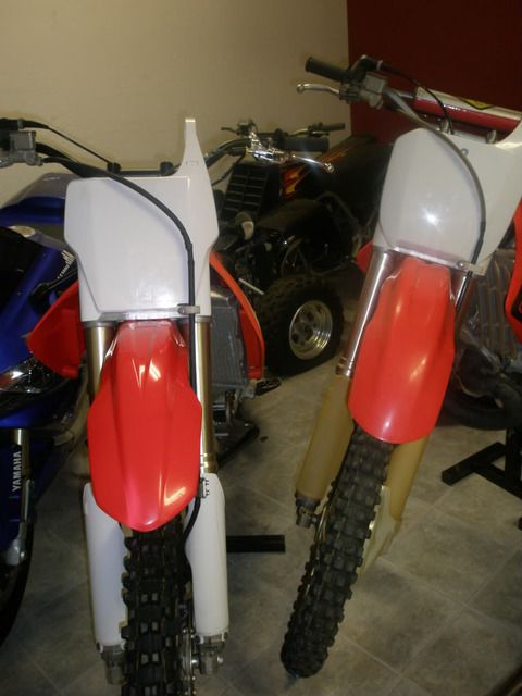
I also installed the ‘04-‘07 front fender and front number plate. The fender was a direct bolt up. Number plate requires custom L bracket and plastic trimming, or drill, tap and a little plastic trimming. I will go over that in a future post.
The other thing I cleaned up was the radiator overflow hose. I used Watts brand clear plastic tubing from the home depot I lost the tag that had the size I know it is the next size larger than 5/16" OD 3/16 ID. About $5 for 20' The original yellowed hose is on the left for reference.
I also installed some aftermarket fork guards. This is one of the few areas I prefer aftermarket over OEM. The oems on their best day are a funky milky white, then they yellow from there. Aftermarkets are crisp white. I installed Polisport brand. The fit was as you may have guessed not quite perfect. I had to drill/file out the mounting holes where the step bolts go. I filed some of the holes ex centrical to get them to fork protectors to move out away from the fork the way I wanted. I presume another aftermarket brand may have a better fit, or another OEM (yami/Suz/Kawi) may have a pure white that fits. The ‘01 SH os on the left, on the right is a low hr ‘02 250.
I also installed the ‘04-‘07 front fender and front number plate. The fender was a direct bolt up. Number plate requires custom L bracket and plastic trimming, or drill, tap and a little plastic trimming. I will go over that in a future post.
The other thing I cleaned up was the radiator overflow hose. I used Watts brand clear plastic tubing from the home depot I lost the tag that had the size I know it is the next size larger than 5/16" OD 3/16 ID. About $5 for 20' The original yellowed hose is on the left for reference.
Great idea with the orings to seal the tube up. Looking forward to more on this. Ive been riding my gen2 250 & like it better than my gen3. The frame seems stiffer & a little crisper on turns, a bit chattery almost but the little extra weight will sort that out. Part of my desire of doing than af is better parts availability, the older bikes get harder every year to get chain sliders, plastics, front brake cable guides, all the common wear parts. Putting the gen 3 plastic on the gen 2 will be great for this. Keep up the good work & look forward to the progress. Dig that brake hose trick too they do get crusty looking.
-
Roostius_Maximus
- Site Admin
- Posts: 4641
- Joined: November 16th, 2007, 3:24 pm
- Location: Mt Nebo, Manitoba, Canada
- Contact:
814cr450, do you have that bike? have any spare pistons / reeds or ignitions?
sorry for the thread drift
sorry for the thread drift
http://www.youtube.com/user/500bigbore
My CR500 Tech Reference... http://sdrv.ms/1a0CIiz
MRE Components... http://sdrv.ms/1bs2zhd
My CR500 Tech Reference... http://sdrv.ms/1a0CIiz
MRE Components... http://sdrv.ms/1bs2zhd
-
maddog1927
- Posts: 313
- Joined: April 4th, 2010, 8:10 am
- Location: Mesa, AZ
In September of ’08 I bought a 2001 CR500 AF. I am big time into 2 strokes and needed a 500 to complete the collection. I also really liked the David Bailey retro style graphics. I thought an AF with the David Baileys sitting in the garage next to my 1985 ATC 250r would look cool. Unfortunately I did not do my research before buying and after I bought the ’01 I discovered that the DB’s were not available for the Gen 2 bikes. That is what initiated the Gen 3 body conversion. When I got the DB’s I was further disappointed that they were orange, not red. The end result was that it did not look like a match pair next to my ATC. With the orange bike my buddies gave me a hard time about having a secret fetish with KTMs.
I found a link on the other site to another site where a guy had done a gen 3 body on his gen 2 cr250.
There are 3 areas that can be converted independently.
’04-’07 number plate.
'02-'07 shrouds (requires tank and custom brackets)
'02-07 side panels (requires '02-'07 air box and custom brackets)
Today I will discuss the easy one, front number plate.
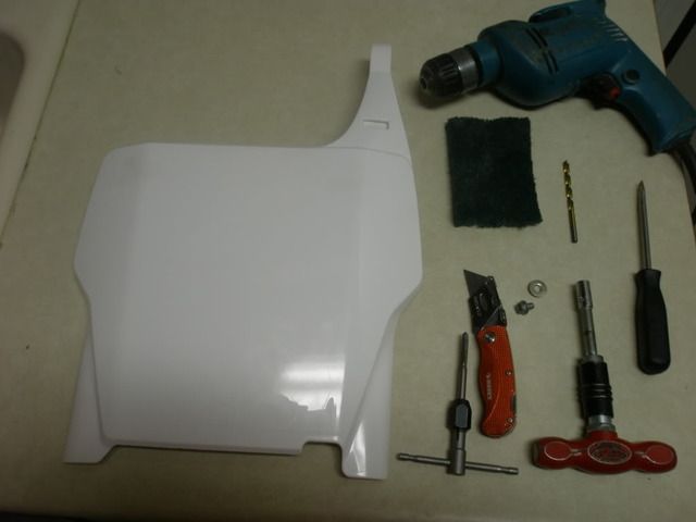
Required tools / components
’04-’07 number plate
Drill
Drill Bit
Tap
Bottom tap (optional)
Flat head screw driver
Utility knife
8mm (5/16”) T wrench, nut driver, socket, whatever you have
Scotch Brite pad
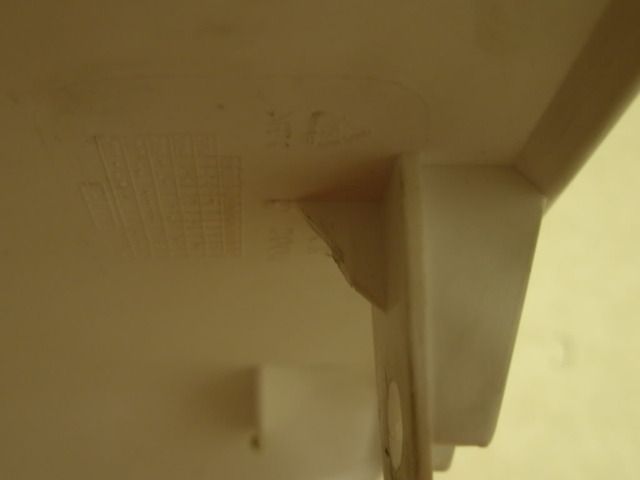
I did this because the DB kit came with an ’04-’07 number plate. First pop the Honda logo off. Flat head screw driver will do. It is held on with double stick tape. Remove tape with utility knife blade, then restore brushed look with scotch brite pad. Next “dry fit” the ’04 + number plate. You will notice that the top will not go far enough back to touch the upper triple. This is because of interference between the ’03- mounting tit on the upper triple. I wanted to retain the ability to use the ’03- number plate, so rather than cut it off, I used a file to file a groove into it allowing space for the support gusset on the ‘04+ plate. I did end up trimming about 1/16” off the support gusset to get a good fit. Now with the number plate in place mark the upper triple where the mounting hole is needed (where the Honda logo was). I used a spring loaded center punch. Now drill a 13/64” hole about 3/8” or 9mm deep. Be careful to keep the drill perpendicular to the upper triple, and do not waller out the hole. Now tap with a 6mm x 1.00 tap. Spin with pressure until it gets a good bite, then let it self feed. Go in ½ turn at a time, then back a ¼ to cut the chips. Since I am doing this as a hobby not production, I take my time and back the tap out on regular basis and blow out the hole and tap. Resistance will tell you when you hit bottom, stop and remove tap. Taps are very hard which equals brittle compounded by the flutes making them very easy to break off in a hole. Since they are so hard drilling them out is not much of an option, especially when broken off in a much softer material. If you have a bottom tap (non tapered tap) it would be good to chase the threads with it so you get fully cut threads to the bottom of the hole. I did not have a bottom tap so I did not do this step.
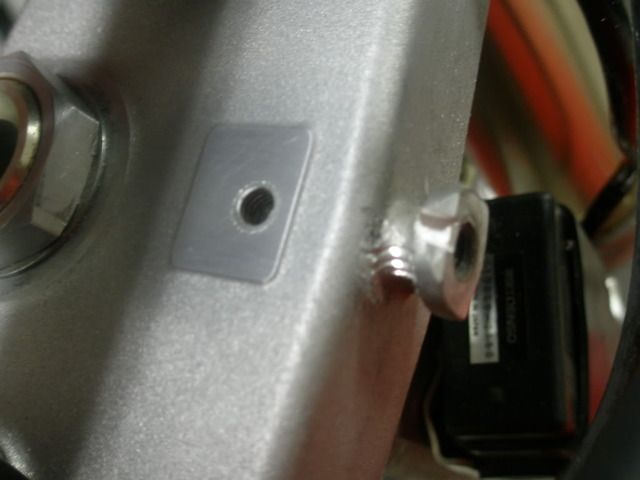
Use a 6 x 1.00 mm x 8mm long flange bolt and step washer to install.
This can also be accomplished by making a little “L” bracket, which is more difficult, you have to hack the support gusset all the way out, and the fit and finish is not as good.
I will cover the other two areas when I get around to redoing them. Don't worry, unlike my "fuel in the spars" idea, this project is a definate go. I already did it, just cleaning it up a bit.
I found a link on the other site to another site where a guy had done a gen 3 body on his gen 2 cr250.
There are 3 areas that can be converted independently.
’04-’07 number plate.
'02-'07 shrouds (requires tank and custom brackets)
'02-07 side panels (requires '02-'07 air box and custom brackets)
Today I will discuss the easy one, front number plate.
Required tools / components
’04-’07 number plate
Drill
Drill Bit
Tap
Bottom tap (optional)
Flat head screw driver
Utility knife
8mm (5/16”) T wrench, nut driver, socket, whatever you have
Scotch Brite pad
I did this because the DB kit came with an ’04-’07 number plate. First pop the Honda logo off. Flat head screw driver will do. It is held on with double stick tape. Remove tape with utility knife blade, then restore brushed look with scotch brite pad. Next “dry fit” the ’04 + number plate. You will notice that the top will not go far enough back to touch the upper triple. This is because of interference between the ’03- mounting tit on the upper triple. I wanted to retain the ability to use the ’03- number plate, so rather than cut it off, I used a file to file a groove into it allowing space for the support gusset on the ‘04+ plate. I did end up trimming about 1/16” off the support gusset to get a good fit. Now with the number plate in place mark the upper triple where the mounting hole is needed (where the Honda logo was). I used a spring loaded center punch. Now drill a 13/64” hole about 3/8” or 9mm deep. Be careful to keep the drill perpendicular to the upper triple, and do not waller out the hole. Now tap with a 6mm x 1.00 tap. Spin with pressure until it gets a good bite, then let it self feed. Go in ½ turn at a time, then back a ¼ to cut the chips. Since I am doing this as a hobby not production, I take my time and back the tap out on regular basis and blow out the hole and tap. Resistance will tell you when you hit bottom, stop and remove tap. Taps are very hard which equals brittle compounded by the flutes making them very easy to break off in a hole. Since they are so hard drilling them out is not much of an option, especially when broken off in a much softer material. If you have a bottom tap (non tapered tap) it would be good to chase the threads with it so you get fully cut threads to the bottom of the hole. I did not have a bottom tap so I did not do this step.
Use a 6 x 1.00 mm x 8mm long flange bolt and step washer to install.
This can also be accomplished by making a little “L” bracket, which is more difficult, you have to hack the support gusset all the way out, and the fit and finish is not as good.
I will cover the other two areas when I get around to redoing them. Don't worry, unlike my "fuel in the spars" idea, this project is a definate go. I already did it, just cleaning it up a bit.
-
maddog1927
- Posts: 313
- Joined: April 4th, 2010, 8:10 am
- Location: Mesa, AZ
Earlier this summer I removed the engine, I had had no issues with it, just wanted to check it out. Prior to removing the engine I checked the compression. It was huffing in the 180 PSI range. The other 2 500s I had at my disposal were huffing 130-140ish.
I will save you guys a couple of posts… Yes I know that compression tests tell very little on a 2 stroke especially when a cheap autozone gauge is used… but I had a gauge, the time, and 3 bikes at my disposal so I did it.
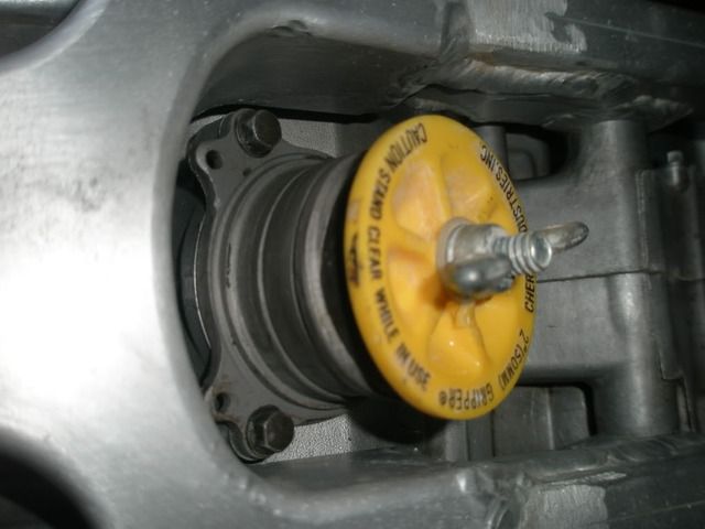
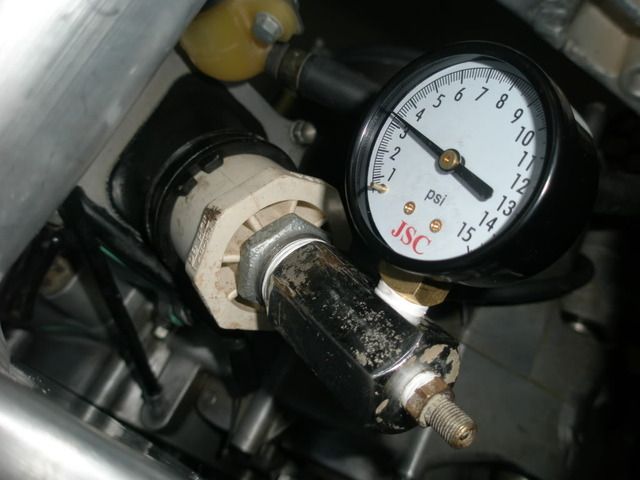
I also did a pressure test on the top end. To do so I put an 1 ½” dollar plug in the exhaust flange to cap it off. I used an 1 ½”x ¾” bushing with a threaded PVC nipple glued into it, and a gauge block screwed onto that at the carb boot to introduce air. I used an air compressor, but a hand pump would be a nice way to keep from over pressurizing. I pumped it up to 4 PSI, it bleed down fast, seemed to be leaking at the exhaust flange and reed cage gaskets. Crank seals are another possibility, I decided to continue with my tear down and inspect. If I needed to rebuild the crank new seals would be going in, if the crank was okay, upon reassembly I would do another PSI check and change the seals if needed.
Note: 1 ½” Dollar plugs also work well to plug off banshee carbs while washing.
I removed the cylinder. Everything seemed tight and in good shape. The exhaust bridge had been properly relieved. It was on the 90 MM bore with a wiseco piston. The previous owner told me it had been ported by Eric Gorr, but he was mistaken. It had TTM porting (stock). The only thing that I could see was that the head gasket was starting to blow in one area.
I took it to my friend Jay’s shop. He is the local banshee guru. He checked out the bottom end, it was okay and I did not need to rebuild. We addressed the head gasket issue by surfacing the head and cylinder. There were low spots in both and the sleeve had dropped slightly. We surfaced the cylinder using a Bridgeport Knee Mill. We clamped the cylinder to the table using gauge blocks under the 4 corners to keep the cylinder square to the table. Then using a “fly cutter” and the X axis power feed, we cut the top of the cylinder a few thousands at a time until it cleaned up. We did the same on the head. I reassembled the engine using new gaskets and did a pressure test. It still bleed down a little. Using a spray bottle with a mixture of dish soap and water I located a leak at the reed valve gasket. I removed and reinstalled using a little ultra black silicone. After the silicone dried, I retested, it held 3 psi overnight. I was happy that it did because it means my crank seals were good so I did not have to replace.
I will try to get some photos of a cylinder being fly cut.
I left the stock porting for the time being
I will save you guys a couple of posts… Yes I know that compression tests tell very little on a 2 stroke especially when a cheap autozone gauge is used… but I had a gauge, the time, and 3 bikes at my disposal so I did it.
I also did a pressure test on the top end. To do so I put an 1 ½” dollar plug in the exhaust flange to cap it off. I used an 1 ½”x ¾” bushing with a threaded PVC nipple glued into it, and a gauge block screwed onto that at the carb boot to introduce air. I used an air compressor, but a hand pump would be a nice way to keep from over pressurizing. I pumped it up to 4 PSI, it bleed down fast, seemed to be leaking at the exhaust flange and reed cage gaskets. Crank seals are another possibility, I decided to continue with my tear down and inspect. If I needed to rebuild the crank new seals would be going in, if the crank was okay, upon reassembly I would do another PSI check and change the seals if needed.
Note: 1 ½” Dollar plugs also work well to plug off banshee carbs while washing.
I removed the cylinder. Everything seemed tight and in good shape. The exhaust bridge had been properly relieved. It was on the 90 MM bore with a wiseco piston. The previous owner told me it had been ported by Eric Gorr, but he was mistaken. It had TTM porting (stock). The only thing that I could see was that the head gasket was starting to blow in one area.
I took it to my friend Jay’s shop. He is the local banshee guru. He checked out the bottom end, it was okay and I did not need to rebuild. We addressed the head gasket issue by surfacing the head and cylinder. There were low spots in both and the sleeve had dropped slightly. We surfaced the cylinder using a Bridgeport Knee Mill. We clamped the cylinder to the table using gauge blocks under the 4 corners to keep the cylinder square to the table. Then using a “fly cutter” and the X axis power feed, we cut the top of the cylinder a few thousands at a time until it cleaned up. We did the same on the head. I reassembled the engine using new gaskets and did a pressure test. It still bleed down a little. Using a spray bottle with a mixture of dish soap and water I located a leak at the reed valve gasket. I removed and reinstalled using a little ultra black silicone. After the silicone dried, I retested, it held 3 psi overnight. I was happy that it did because it means my crank seals were good so I did not have to replace.
I will try to get some photos of a cylinder being fly cut.
I left the stock porting for the time being