Page 1 of 2
Hondadug's 2004 CR500AF build
Posted: October 29th, 2013, 12:54 pm
by Hondadug
Posted: October 29th, 2013, 1:12 pm
by Hondadug
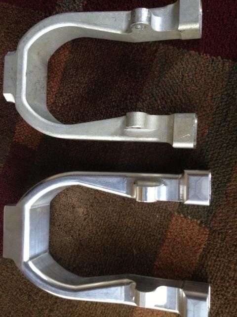
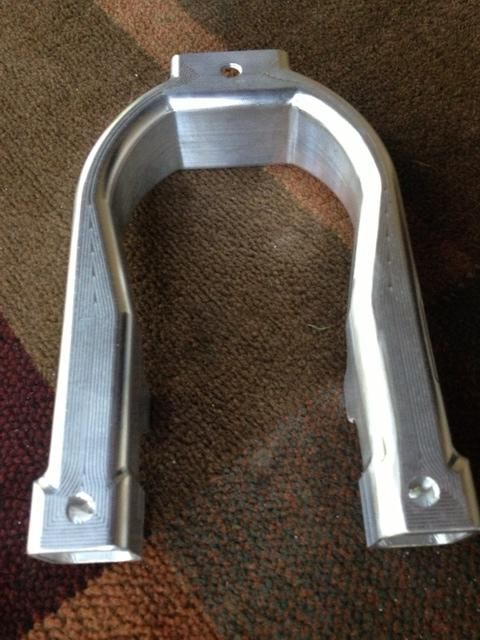
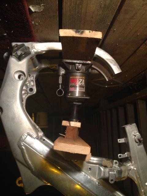
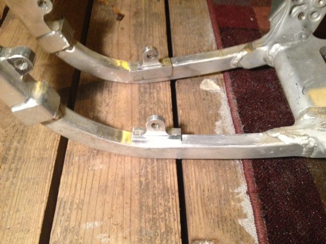
My Y is put it as you have seen before, but fits the 2002-2004 frame. If I ever make another one I am not going to integrate motor mounts. That part sucked and the down tube holder at the bottom rubbed the motor so I had to sand it down a bit. Also the down tube slot was a bit wide so I had to put in a bit of extra metal. That was my mistake because I was messing with a different frame and cut the down tubes out. We left it larger to see what fit best and if we do it again, we will have a better fit.
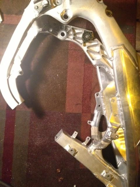
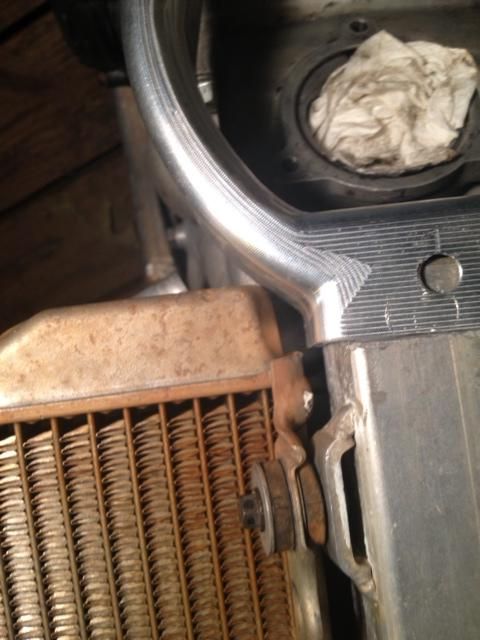
The radiator hit a bit, but I massaged it into submission
I sanded off the bottom motor mounts while being careful not to cut into the tubes
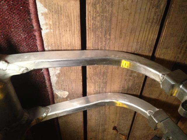
I got some billet mounts off a auction site you know and used two for the lower mounts.
Posted: October 29th, 2013, 1:19 pm
by Hondadug
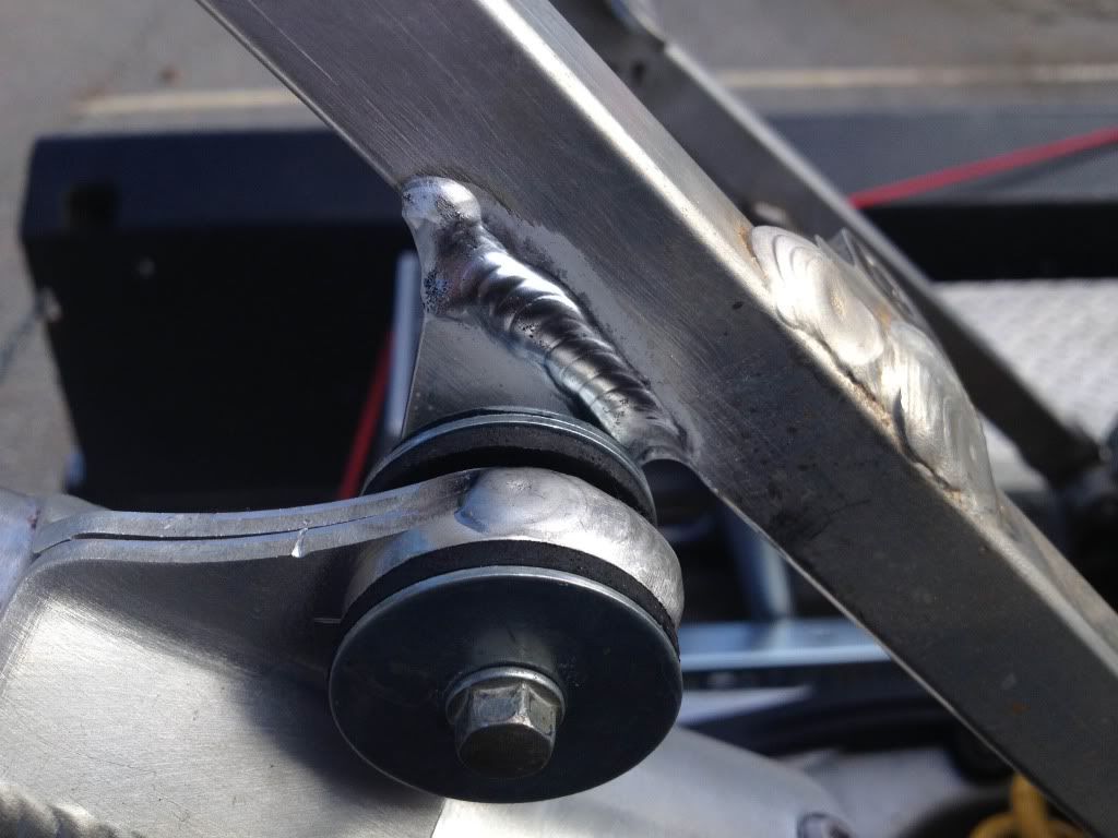
Time to weld
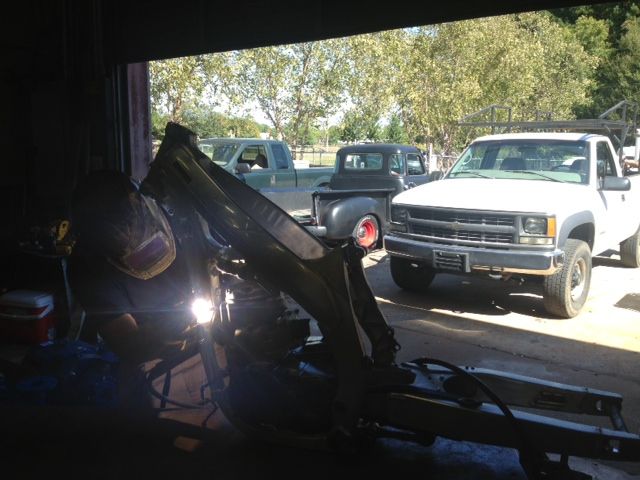
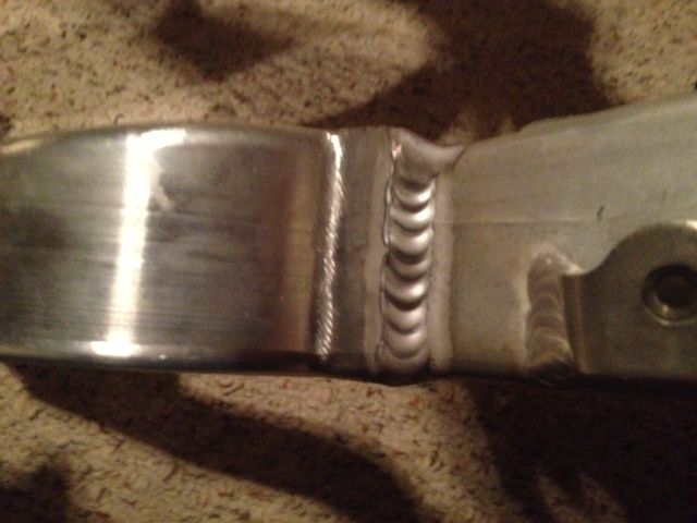
Well, I guess I need to take more weld pics. He did a really nice job so I want to make sure and show some
Posted: October 29th, 2013, 1:31 pm
by Bronson
Great post. Looking forward to seeing more. I'm in the process of getting everything I need for my 2004 CRF450 conversion and would be interested in a Y if you are gonna make them.
Posted: October 29th, 2013, 3:11 pm
by Hondadug
We could probably make one for ya. The only thing is we need to change some dimensions and I want to get rid of the front motor mounts so you can be more flexible with position. With that said, I would probably want to try it on another frame before I hook anybody up with one. I don't want you to be upset with what you get. That may be too long for you. I have another frame here, but I cut the down tubes off when I was trying something different. Don't do that. I am also working on making an airbox adapter. I'm roughing out one now. We'll see how that goes.
Posted: October 29th, 2013, 4:42 pm
by blackz34
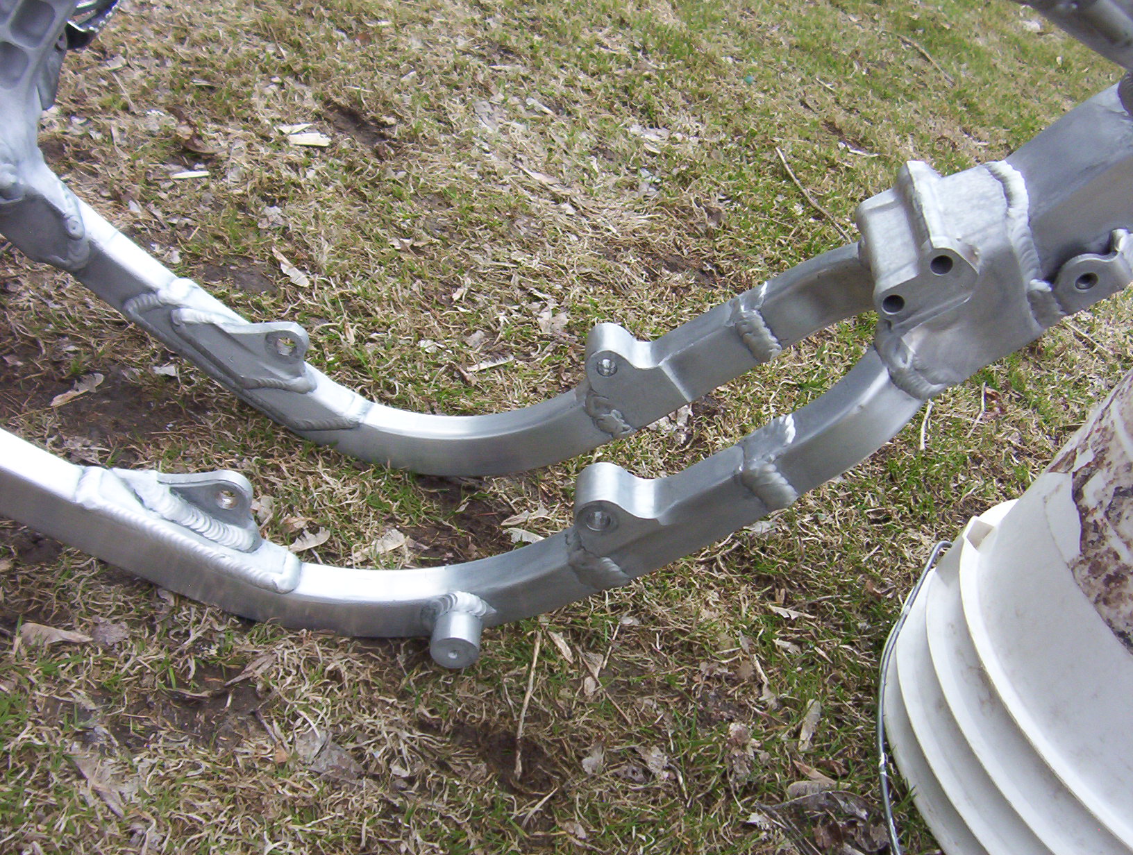
I like your Y too. If I can make a suggestion, instead of the "Pocket" that rubbed the motor, do the opposite, make that part go inside the frame. It will give you more cleareance all around the tube. I would also leave the motor mounts on the Y , less welding = less stress on the part--> less chance to crack.
I did something similar on mine, not a complete Y, but my extension have the mount incorporated in them (you can do wonders with just a grinder an a press drill!!)
I hope the pics works:
https://skydrive.live.com/embed?cid=ED6 ... BuM4abN0aw
edit: link seems to work for me and if I click on the image it gets bigger.
Posted: October 31st, 2013, 9:48 am
by AlisoBob
Posted: October 31st, 2013, 12:57 pm
by blackz34
Thank you Bob !
Posted: October 31st, 2013, 9:16 pm
by Hondadug
Black,
I hear ya on that. I guess I first saw the pockets and it really appealed to me and stuck with it. The designing over the phone caused the rub. But you bring up valid points. One difference about your inserts and my y is that your tubes will line up. If I make inserts instead of pockets I need to design it so they line up with the weird angles the tubes come in. Possible but more difficult for my first try.
Your insert design is so much more straight forward. I'm curious to hear Bob's take on the strength differences between the two cus I saw he posted before he didn't like billet y's due to excessive rigidity.
Posted: October 31st, 2013, 9:39 pm
by Hondadug
Posted: November 6th, 2013, 7:23 am
by Hondadug
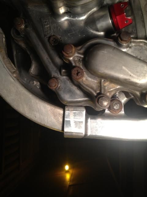
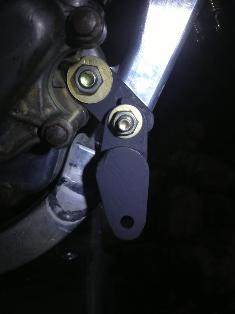
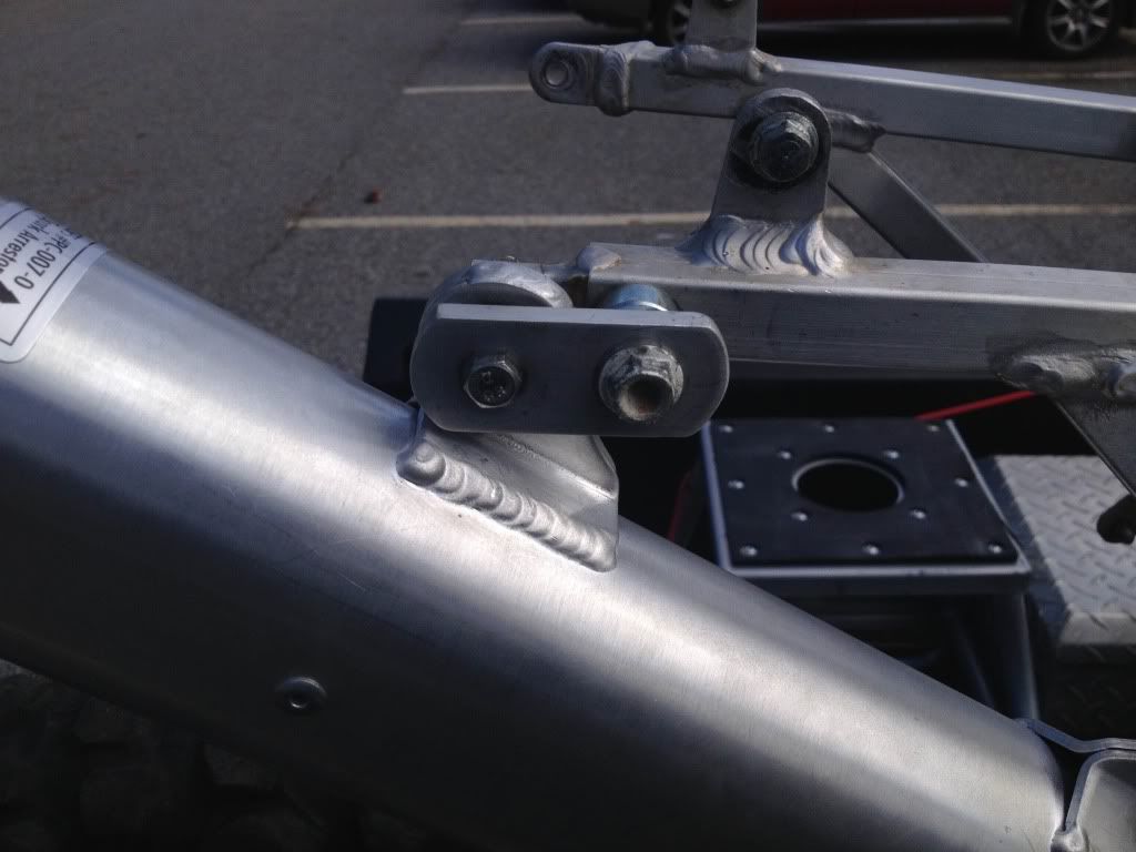
I tried something a bit different for the front exhaust mount. Some may like it some may not, but I liked the simplicity. It bolts to the front motor mount and works really well.
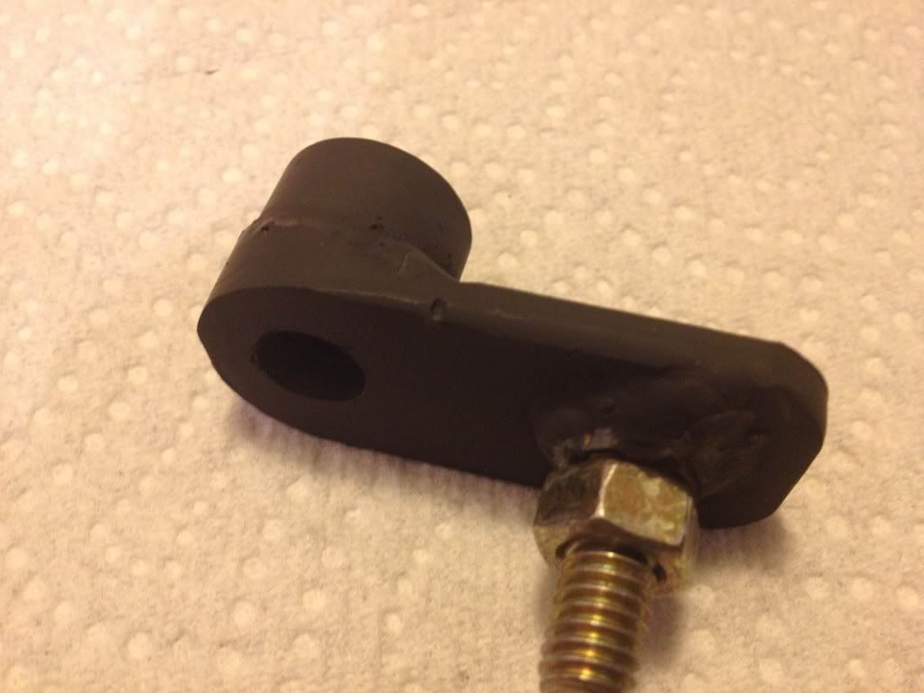
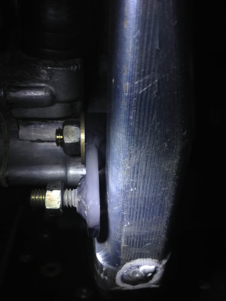
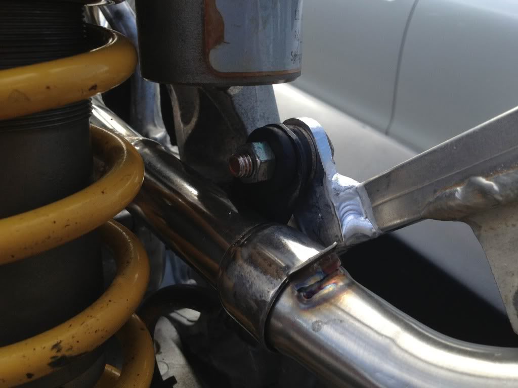
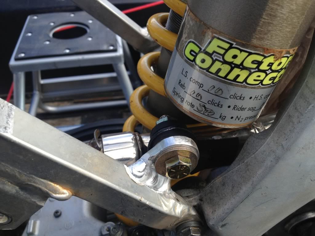
Here is my silencer mount setup. What I did is make a mount from a grommet I found at Lowes. It was really easy to make and the rear mount was no good on my used pipe anyway. I wanted to mount to the subframe bolt, but I couldn't get it to line up and still get a nut on. I like how this worked out anyway. For the rear silencer mount I just picked up the rear fender bolt and made a bracket to bolt to the original silencer mount as well.
and YES, I have put a washer on my pipe mount.
Front silencer mount
Rear silencer mount
Posted: November 6th, 2013, 7:56 am
by Hondadug
Posted: November 6th, 2013, 12:28 pm
by Hondadug
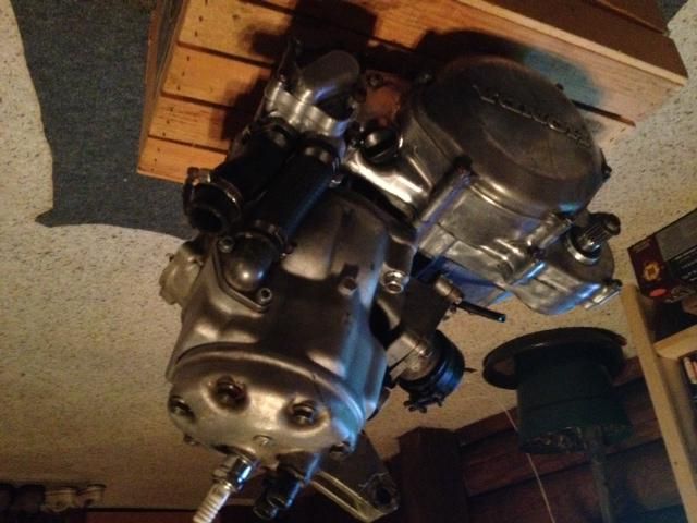
I cleaned off the black paint from the 1990 engine and ready to put in
Posted: November 6th, 2013, 5:40 pm
by ThaBing
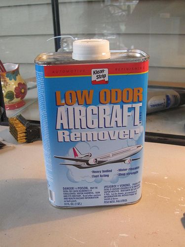
How did you go about getting the paint off from the motor??
Posted: November 7th, 2013, 6:26 am
by Hondadug
Buy this stuff from lowes. Designed to take paint of aluminum. It's an acid so use good gloves and do it outside. Most of the paint will just curl up and fall off. Some areas u have to scrape or use a wire brush. I used gallons on a1950 fuel truck that I think was painted once a year looking at the layers. It's powerful stuff
Posted: November 13th, 2013, 4:21 pm
by cowboyona426
I've heard the later model cases are actually clear coated, any plans to coat your cases to keep them from getting corrosion?
Posted: November 13th, 2013, 5:23 pm
by Roostius_Maximus
1995+ cases are bare, no cases have ever been clear
Posted: November 14th, 2013, 9:30 am
by cowboyona426
Roostius_Maximus wrote:1995+ cases are bare, no cases have ever been clear
Hmm interesting. So if a guy was to remove the paint from his cases like OP did would he have to worry about any corrosion issues? I kind of like the look of the bare cases but if it's going to be a maintenance nightmare then I'll just leave mine black.
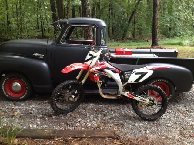
Side note- OP I LOVE your 5 window Chevy!

Posted: November 14th, 2013, 12:37 pm
by Kuma
Right side case on some 89 and older (waterpump/clutch case) are mag, they will corrode especially when in contact with salt water, aluminum, not so much

Posted: February 15th, 2014, 9:01 am
by Hondadug
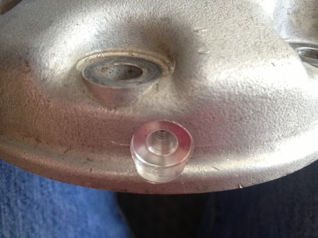
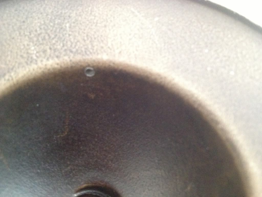
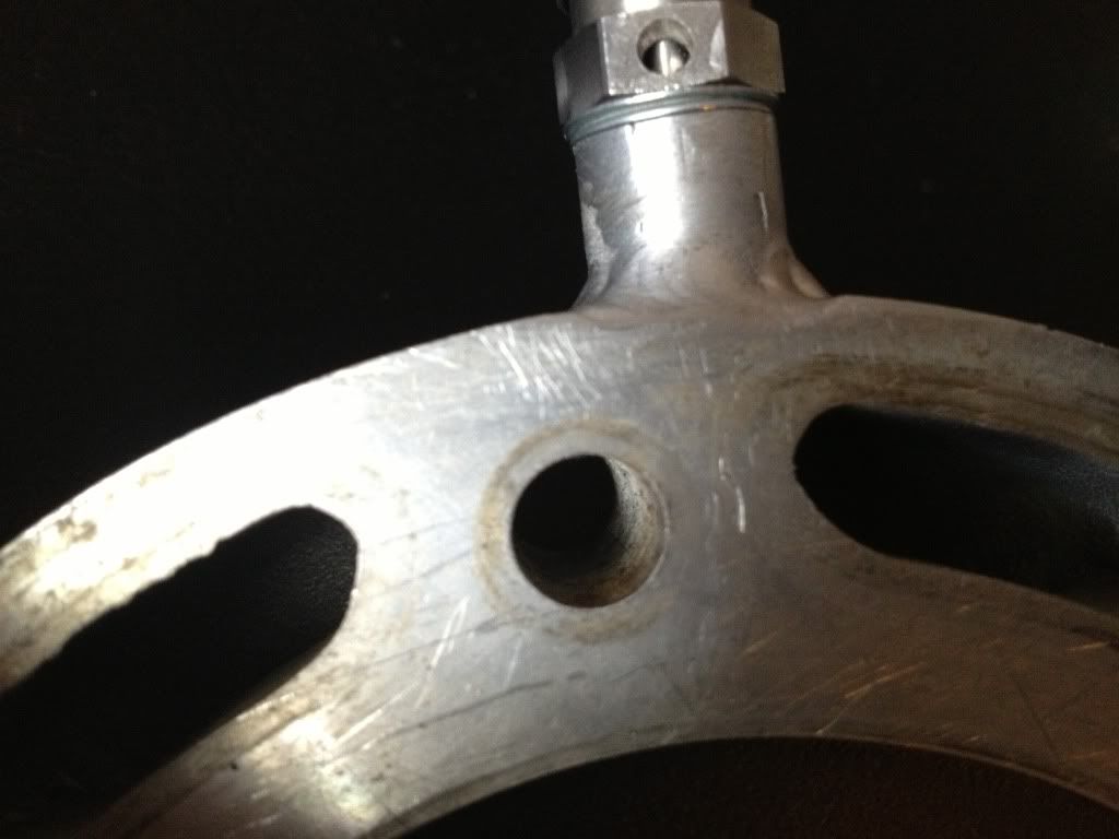
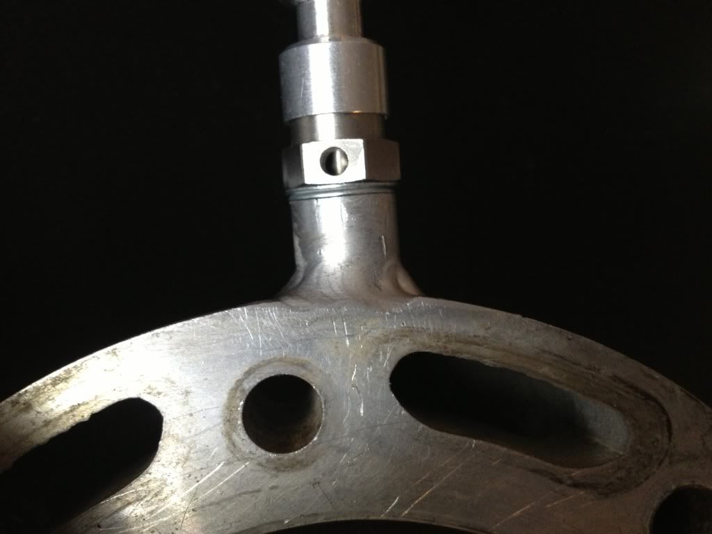
Posted: February 15th, 2014, 2:16 pm
by Kuma
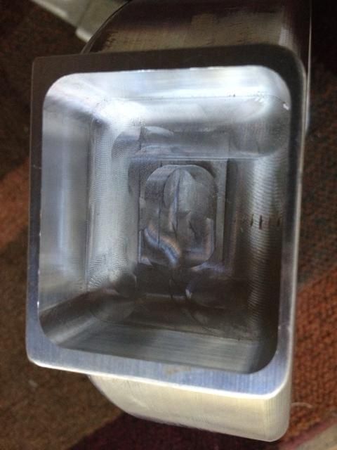
I'm no roosty but it doesn't look like you will have any problems, I would use a flat plate, and a sheet of 400 sand paper and lap it a bit to make sure it is still nice and flat, if you don't get full contact, use something coarser and get it flat then work your way back to 320 or 400 grit.
Posted: February 18th, 2014, 8:07 am
by Roostius_Maximus
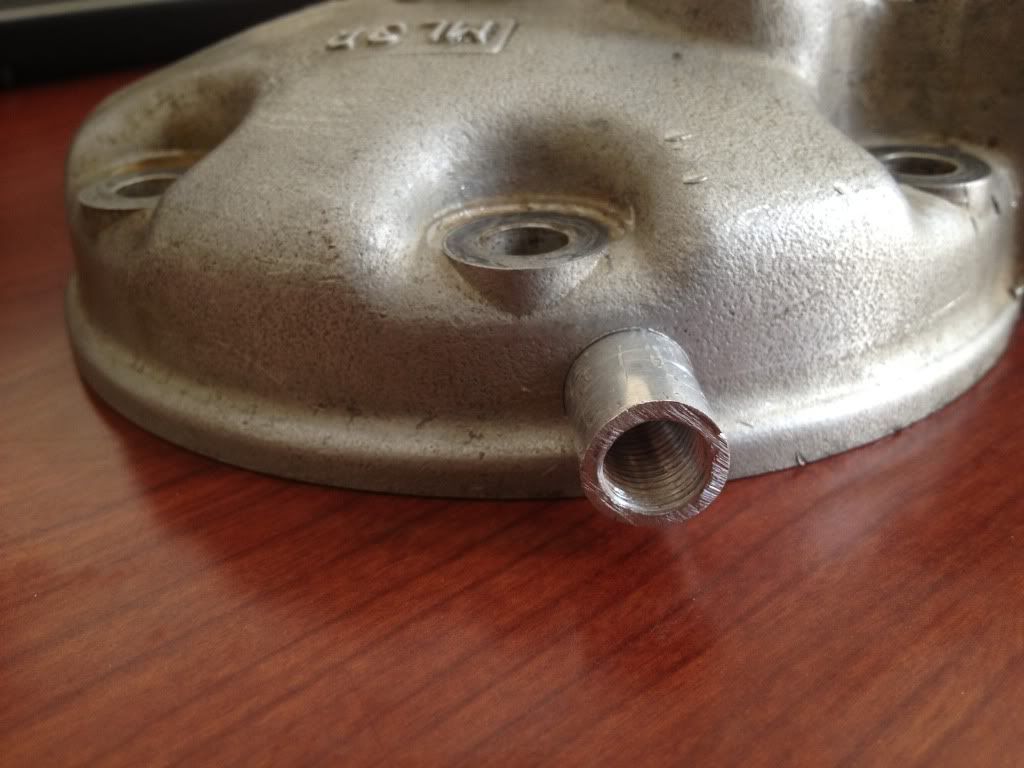
ya, it don't look bad. I prefer to do the chamber entrance as a 90* passage and come out of the squish band, it'll work.
Posted: February 23rd, 2014, 11:36 pm
by Hondadug
Thanks for the replies guys. I'm not familiar with the term "squish". Could somebody fill me in?
Posted: February 24th, 2014, 7:00 am
by Roostius_Maximus
Posted: February 24th, 2014, 8:51 am
by lms1977
it is the flat angle part on the dome part of the head before the rounded dome, the distance between that and the piston is what there talking about if that makes sense