Gen 2 CR500AF build started on 01.04.2012

Building Tips, Suspension Set Ups, Conversion Parts .... Build to your Heart's Content!
User avatar
fmikhele
Posts: 147
Joined: April 10th, 2012, 7:26 am

Gen 2 CR500AF build started on 01.04.2012

Post by fmikhele »

Hey guys... Wicked site!

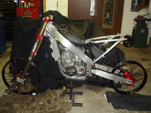
I am currently building a Gen 2 CR500AF from a CR250 donor. The donor motor is a 1995 CR500. I was waiting on acceptance so the build is already well under way...

Here is where I am at:
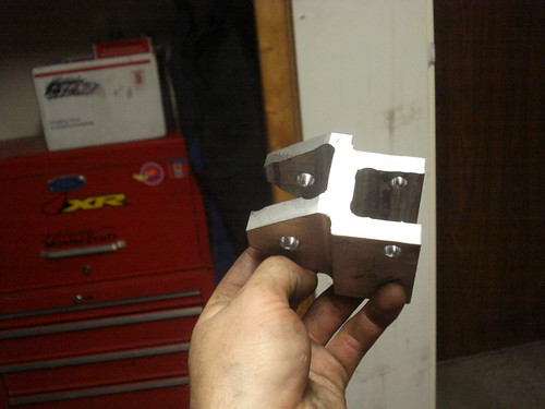
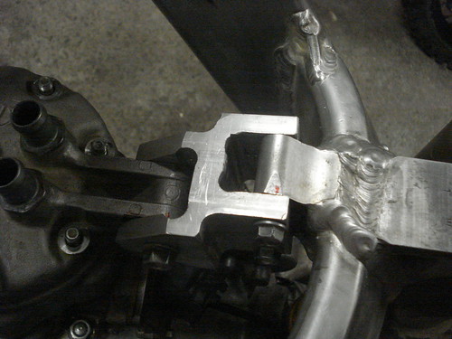
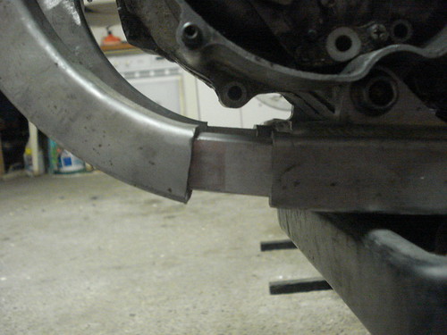
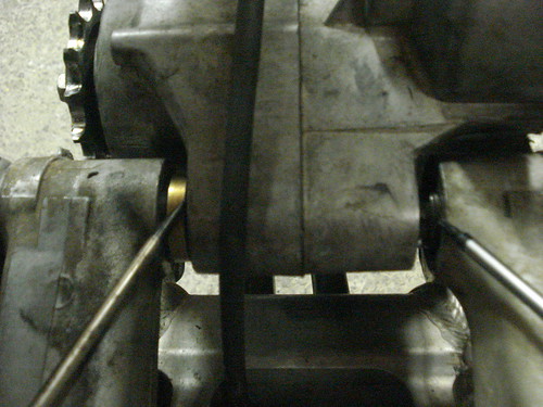
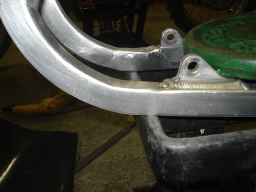
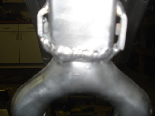
"Y" / cradle (a head of the lower engine mounts) cut and relocated.
6061 Inserts machined from bar stock for the cradle
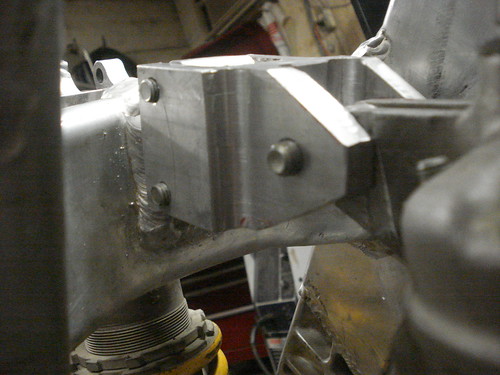
6061 billet head-stay 75% done (will post pics)
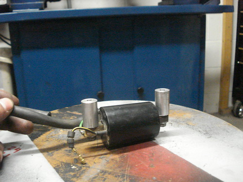
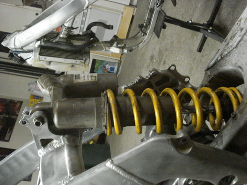
1" 6061 round stock coil mounts
Acquired the Gen3 CR250 air boot for the proper fitment
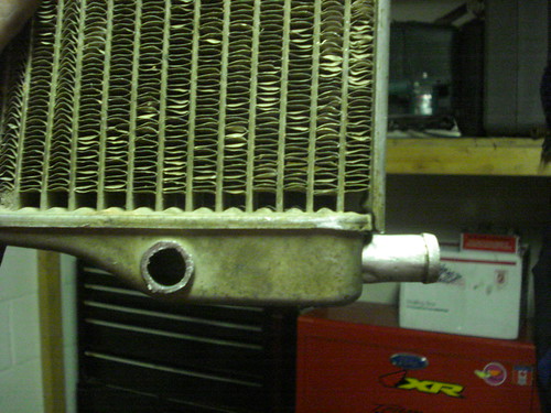
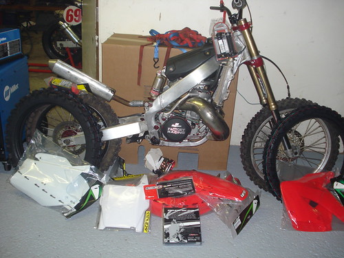
Started to modify the rads, but found some epoxy from the previous owner so I am trying to track down some new rads (anyone have some kickin' around?). The fitment looks good on the bike, I plan to machine spacers for the lower mounts to ensure clearance of the "Y"
Plan to re-use front mounts.
Rear Shock in blown, so taking it to MCR for a rebuild.

Motor History:
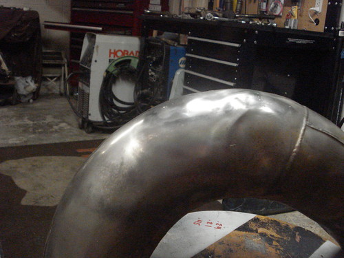
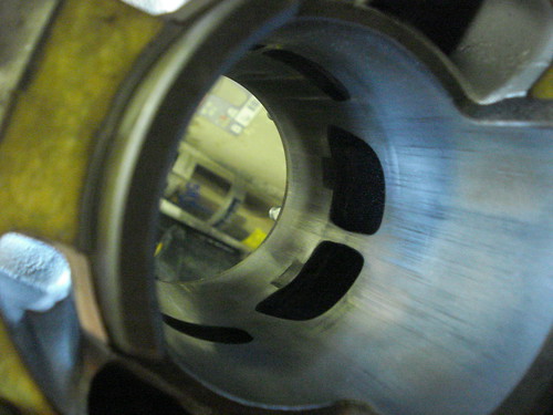
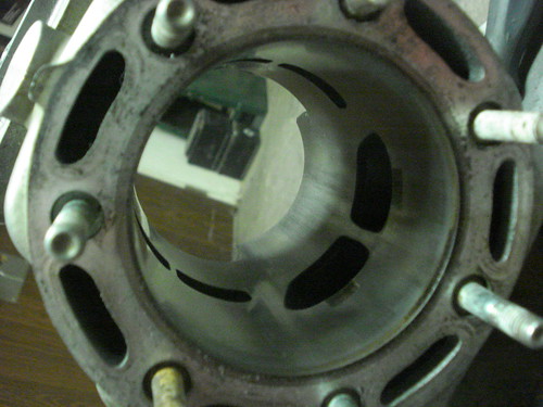
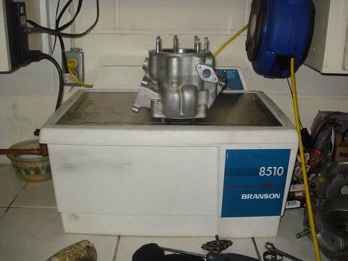
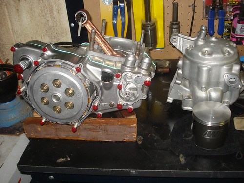
The main chamber of the pipe from the CR500 was dented to HALF its original diameter when I went to buy the donor bike, So when I went to test drive it, it had no top end. I didn't think anything of it because of the big dent in the pipe would definitely effect that... So when I got the bike home I was going over everything (carb, reeds, etc etc) I took out the reed cage to discover a giant crack in the intake side piston skirt. So the engine is currently full dismantled and awaiting new bearings, crank rod, piston etc etc. For the pipe, I machined up a couple plugs and heated it up with about 20psi of air and got 99% of that dent out. Would like to get a new pipe but 1. I am Italian and cheap and 2. dont feel like spending $200-300 on a new one. Unless someone on hear has a lead on something cheaper?? Measured the cylinder (STD bore) with a dial-bore within spec but we'll see how it looks after a good honing...

Need to Do:
Silencer Mounts (this weekend)
Machine Swing arm spacers (Leaning towards machining 1 piece inserts for side cases rather then spacers, input??) (this weekend / next week
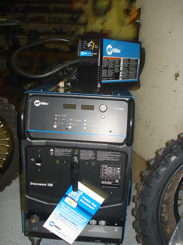
Weld it! (Hopefully next weekend)
Powder coat anything and everything I can think of...

Need to acquire
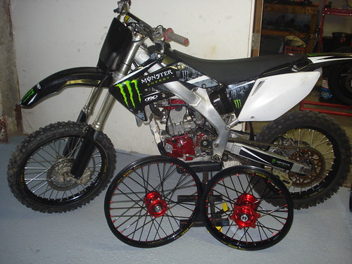
new plastics and graphics
Excel rims (anyone have any or know somebody looking to sell a set for a decent price?)

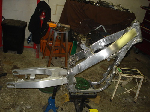
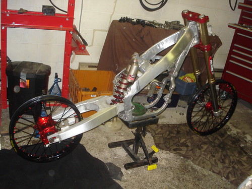
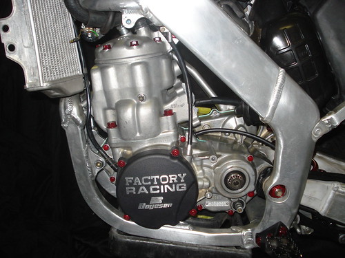
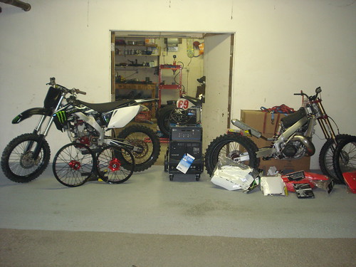
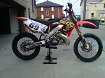
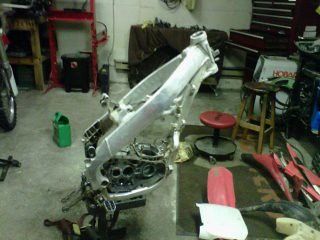
Here all the only photos I have so far:
Image
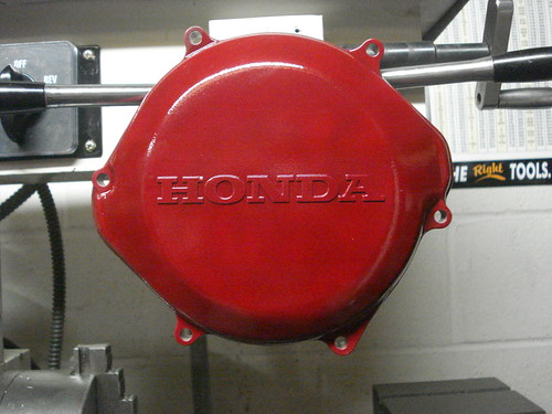
Bike1 by fmikhele, on Flickr
Image
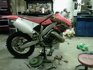
bike2 by fmikhele, on Flickr

Reference Builds:
Obviously everything on this site, but for visual people this guy did a pretty good job documenting his build on video ---> http://www.youtube.com/watch?v=1HJz5WZldH4

Welding tips (obvious but helps)
http://www.youtube.com/watch?v=FadO0hqTaN0

Thanks guys! Look forward to any feedback...
User avatar
fmikhele
Posts: 147
Joined: April 10th, 2012, 7:26 am

Post by fmikhele »

So the clutch went in my car last weekend, so nothing got done on the bike. This weekend was pretty productive the head stay is more-less done (minor clean up needed)

Image
DSC00894 by fmikhele, on Flickr

Image
DSC00890 by fmikhele, on Flickr

Image
DSC00891 by fmikhele, on Flickr


Got the coil mounts done

Image

Frame Extenders are in

Image
DSC00889 by fmikhele, on Flickr

Figured out the Swing arm spacers (6mm left & 3.75mm right)

Image
DSC00901 by fmikhele, on Flickr

Left Rad. Re-directed

Image
DSC00902 by fmikhele, on Flickr

Here is a pic of the pipe after the dent was popped, I wish I had a pic of the before (was crushed to have the diameter it is now). It looks like the heat stress marks will polish out, which is nice because the pipes for these things are $$$.

Image
DSC00900 by fmikhele, on Flickr

Did a test peace with Eastwood's new powder called "anodized red." I did not polish the cover before powder coating it, so I am going to try that on the next piece to try to get it looking more like an anodize part.

Image
DSC00893 by fmikhele, on Flickr

I am also rebuilding a 2004 crf250 right now and had them sitting side by side and decided to see if the CRF suspension would fit and it does. So I am going to run the CR500AF and the 01 CR250 suspension on the CRF250 (my spare bike).

Image
DSC00892 by fmikhele, on Flick

Here are some pic's of the cylinder. Checked it with the dial-bore gauge and it checked out but I will check it again after getting it honed.

Image
DSC00897 by fmikhele, on Flickr

Image
DSC00895 by fmikhele, on Flickr

Finally taking the CRF suspension (front and back), the crank / new Pro-X rod and the cylinder/Wiseco Piston (Std bore) up to MRC for work.

Image
DSC00903 by fmikhele, on Flickr

So I believe all the cutting and fitting is now done, and it is just a matter of cleaning everything up and prepping for welding, which I planned to do next weekend. Something has now come up and won't say much other then there may be 2 CR500AF's in my garage soon enough :lol:

I am still trying to track down some excel, D.I.D COMPLETE wheels for the beast if anyone has any leads?!?!?
Last edited by fmikhele on May 9th, 2012, 8:46 am, edited 2 times in total.
User avatar
AlisoBob
"Hoon-father"
Posts: 15404
Joined: May 31st, 2007, 6:39 pm
Location: Aliso Viejo Ca

Post by AlisoBob »

I'm all into stiff headstays, but that thing looks like it came off the Titanic.... You sure the tank is going to fit?
Last edited by AlisoBob on April 29th, 2012, 12:29 pm, edited 1 time in total.
User avatar
fmikhele
Posts: 147
Joined: April 10th, 2012, 7:26 am

Post by fmikhele »

Stock and oversize tank fit like a glove. Its tight fitting like everything else on the bike, but will work. From what I've read and the pictures I've seen a lot of people over look the purpose of the head stay and it results in cracked frames (assuming all welds were properly done). Also like I said in my intro, I'm Engineer and like to over design, but would have to agree the factor-of-safety is most likely a 10. Thanks for your input Bob...
User avatar
AlisoBob
"Hoon-father"
Posts: 15404
Joined: May 31st, 2007, 6:39 pm
Location: Aliso Viejo Ca

Post by AlisoBob »

fmikhele wrote:Figured out the Swing arm spacers (6mm left & 3.75mm right)

The Gen 3 CR250 (02-07) uses a 49mm bushing on the left and a 54mm bushing on the right. To do the CR500 engine swap, you move the right one over to left and get a 59mm for the right side and you are done.

Part# for the 59mm bush is 52141-KZ4-J40.

It these measurements work out for a Gen 2, it would makr for a better installation.
User avatar
fmikhele
Posts: 147
Joined: April 10th, 2012, 7:26 am

Post by fmikhele »

The spacers in the picture were there to make sure the sprockets were in line with each other, but I was going to machine new inserts for the cases so that I could still order a swing arm bushing kit for the 01 CR250 and not have to change a thing.

Also I measured both bushings for the 01 and believe they were both 49mm (right & left)??
User avatar
AlisoBob
"Hoon-father"
Posts: 15404
Joined: May 31st, 2007, 6:39 pm
Location: Aliso Viejo Ca

Post by AlisoBob »

Whats the combined bushing + your spacer legnths?

The point I'm trying to get across to you is that there are OEM parts that you can use, and not nigger-rig something together instead.
User avatar
fmikhele
Posts: 147
Joined: April 10th, 2012, 7:26 am

Post by fmikhele »

On the way...

Image
Rims by fmikhele, on Flickr
User avatar
fmikhele
Posts: 147
Joined: April 10th, 2012, 7:26 am

Post by fmikhele »

Sorry for the delay Bob... From what I've read on here the GEN 1 & GEN 2 swing-arm spacers are the same. If this is true then this is what I need...

The LHS is: 49mm (bushing) + 7mm (spacer) = 56mm
The RHS is: 49mm (bushing) + 4mm (spacer) = 53mm

For the spacers I referred to the "Gen 1 A/F Conversion Drawings and Instructions!!" under instructions for the correct spacer measurements (7mm & 4mm).

So at this point I believe the best alternative is to machine up some engine case inserts.
User avatar
AlisoBob
"Hoon-father"
Posts: 15404
Joined: May 31st, 2007, 6:39 pm
Location: Aliso Viejo Ca

Post by AlisoBob »

fmikhele wrote:The LHS is: 49mm (bushing) + 7mm (spacer) = 56mm
The RHS is: 49mm (bushing) + 4mm (spacer) = 53mm
These are the CR125 bushings...


1 52141-KZ4-J40 Bushing ( long side, 59mm)


1 52142-KZ4-J40 Bushing ( short side, 54mm)

I think there will work as the CR500 and CR125 engines share the same rear case width.
User avatar
fmikhele
Posts: 147
Joined: April 10th, 2012, 7:26 am

Post by fmikhele »

Here is the frame all welded and starting clean up of the welds

Image
DSC00925 by fmikhele, on Flickr

Image
DSC00924 by fmikhele, on Flickr

Image
DSC00920 by fmikhele, on Flickr

Finally time to start rebuilding the engine :devious: Here is the cylinder getting ready for the ultrasonic cleaner.

Image
DSC00922 by fmikhele, on Flickr
kevin_s
Posts: 284
Joined: May 2nd, 2011, 6:00 pm

Post by kevin_s »

AlisoBob wrote:
fmikhele wrote:Figured out the Swing arm spacers (6mm left & 3.75mm right)

The Gen 3 CR250 (02-07) uses a 49mm bushing on the left and a 54mm bushing on the right. To do the CR500 engine swap, you move the right one over to left and get a 59mm for the right side and you are done.

Part# for the 59mm bush is 52141-KZ4-J40.

It these measurements work out for a Gen 2, it would makr for a better installation.

Yes,those worked on my gen 2 also ..
User avatar
fmikhele
Posts: 147
Joined: April 10th, 2012, 7:26 am

Post by fmikhele »

Thanks for the reply, I ordered the proper bushing and they are ready to go... :headbang:
User avatar
hoofarted
Posts: 2628
Joined: July 2nd, 2007, 8:48 am
Location: Rancho Cucamonga, CA

Post by hoofarted »

Lemme know how those bushings work out. I did my conversion before this knowledge as those bushings were used for the Gen3's. I have SS spacers on mine. 4mm and 6mm.
The CR500 is an acquired taste. If you don't like it, acquire some taste...

Image
User avatar
fmikhele
Posts: 147
Joined: April 10th, 2012, 7:26 am

Post by fmikhele »

Got the Engine Bottom end done! Researching the installment of a wiseco piston in the cr500. Reading a lot about drilling the lube holes in the piston and the relief of the exhaust bridge. Some people do, some people dont... I rebuilt countless engines with wiseco pistons and have never done this nor had a problem. However, this is my first cr500 build and I would like to get it right. So as of right now I am stumped on which direction to go!?!?

The second thing I have been researching is the digital ignition up grade from the cr250's. I have the ignition set up for a gen 1 and gen 2 cr250. From what I have read these are moreless a bolt on (have to machine the back of the stator plate) and ride set up, but the gen 3 cr250 require tweaking on the slots on the stator plate for timing. Is this correct?

Here is a pic of the lower end

Image
DSC00928 by fmikhele, on Flickr


Got everything back from MCR and my new rims from FASTERUSA

Image
DSC00929 by fmikhele, on Flickr
User avatar
AlisoBob
"Hoon-father"
Posts: 15404
Joined: May 31st, 2007, 6:39 pm
Location: Aliso Viejo Ca

Post by AlisoBob »

You ALWAYS have to chamfer the ports, and relieve the bridge.

With a forged piston, you should drill the lube holes.

Dont chance it....

Do it.
User avatar
fmikhele
Posts: 147
Joined: April 10th, 2012, 7:26 am

Post by fmikhele »

Thanks Bob. For the relief what clearance am I looking for? And what is the best way to measure it? Would you place the piston ring half way down the bridge and measure? I say half way because the relief is an elliptic shape to help the ring travel past the bridge so theoretically the greatest clearance should be half way down the bridge....

Do you have any input on the CR250 digital ignition upgrade?
User avatar
fmikhele
Posts: 147
Joined: April 10th, 2012, 7:26 am

Post by fmikhele »

Engines in!!

Image
DSC00941 by fmikhele, on Flickr

Image
DSC00939 by fmikhele, on Flickr

Waiting on parts... Should be able to fire it finally this weekend!!!!! :nanna:
User avatar
Kuma
Posts: 854
Joined: February 7th, 2010, 8:26 pm
Location: Norco, Cali

Post by Kuma »

Yiou going to run that on rail road tracks :wink:
Gen 2 AF, yes it's a SH, so I can call it an AF Damm it!
User avatar
fmikhele
Posts: 147
Joined: April 10th, 2012, 7:26 am

Post by fmikhele »

Waiting on parts... Should be able to fire it finally this weekend!!!!! Nanna
This isn't how you ride your bikes in cali? :cool:
User avatar
fmikhele
Posts: 147
Joined: April 10th, 2012, 7:26 am

Post by fmikhele »

Its Alive.... Sounds Mean :twisted: Unfortunately I have a leak coming for the left side rad :? So Ill see what I can do about that this weekend although I'll be pretty busy with all these goodies!!! CHRISTMAS CAME EARLY :D :D :D

Image
DSC00945 by fmikhele, on Flickr

Image
DSC00948 by fmikhele, on Flickr

Image
DSC00946 by fmikhele, on Flickr

Image
DSC00947 by fmikhele, on Flickr
User avatar
fmikhele
Posts: 147
Joined: April 10th, 2012, 7:26 am

Post by fmikhele »

Almost there...

Image
DSC00949 by fmikhele, on Flickr
kevin_s
Posts: 284
Joined: May 2nd, 2011, 6:00 pm

Post by kevin_s »

Looking good,I miss my gen 2.
User avatar
warrnum
Posts: 73
Joined: March 14th, 2012, 7:22 am

Post by warrnum »

Great work fmikhele, wow some guys on here have some skills, its amazing and fantastic what they know and how they share their knowledge and experiences. The bike is looking great mate, looking forward to seeing the finished product.
User avatar
fmikhele
Posts: 147
Joined: April 10th, 2012, 7:26 am

Post by fmikhele »

Thanks Guys. Have all the parts, just need to find the time...
Post Reply