CR500 Engine Build Pictorial Part 4
Posted: January 14th, 2011, 9:19 am
This segment will deal with cylinder prep, piston selection and
installation.
The stock CR500 cylinder is unique in that it uses an unplated steel
sleeve.
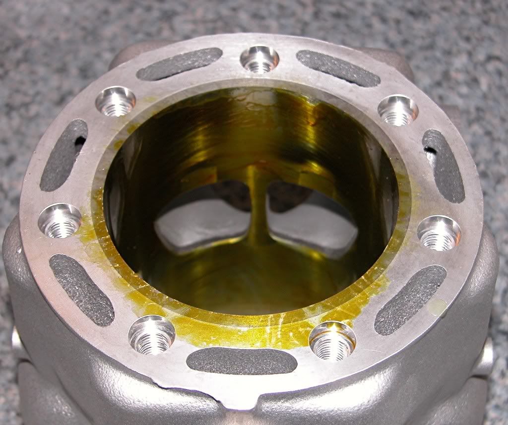
This is what the cylinder looks like right out of the box. Note the sprayed on
plastic protective coating.
Since this engine is being built for MX racing, I decided to have it ported and
machined specifically for that purpose. The port work is designed to up the
power but smooth the "hit" making the bike faster but easier to ride.
Even though the cylinder is brand new, it was bored .001 over to ensure a
perfectly concentric bore. In addition to the port work, the base was
machined to lower the ports (alter the timing) and the intake inlet and
exhaust outlet were matched to the VForce and exhaust flange respectively.
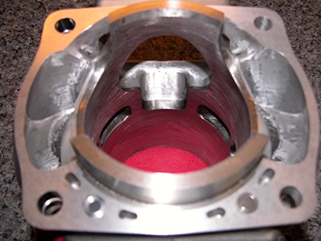
Reworked inlet
Reworked exhaust ports
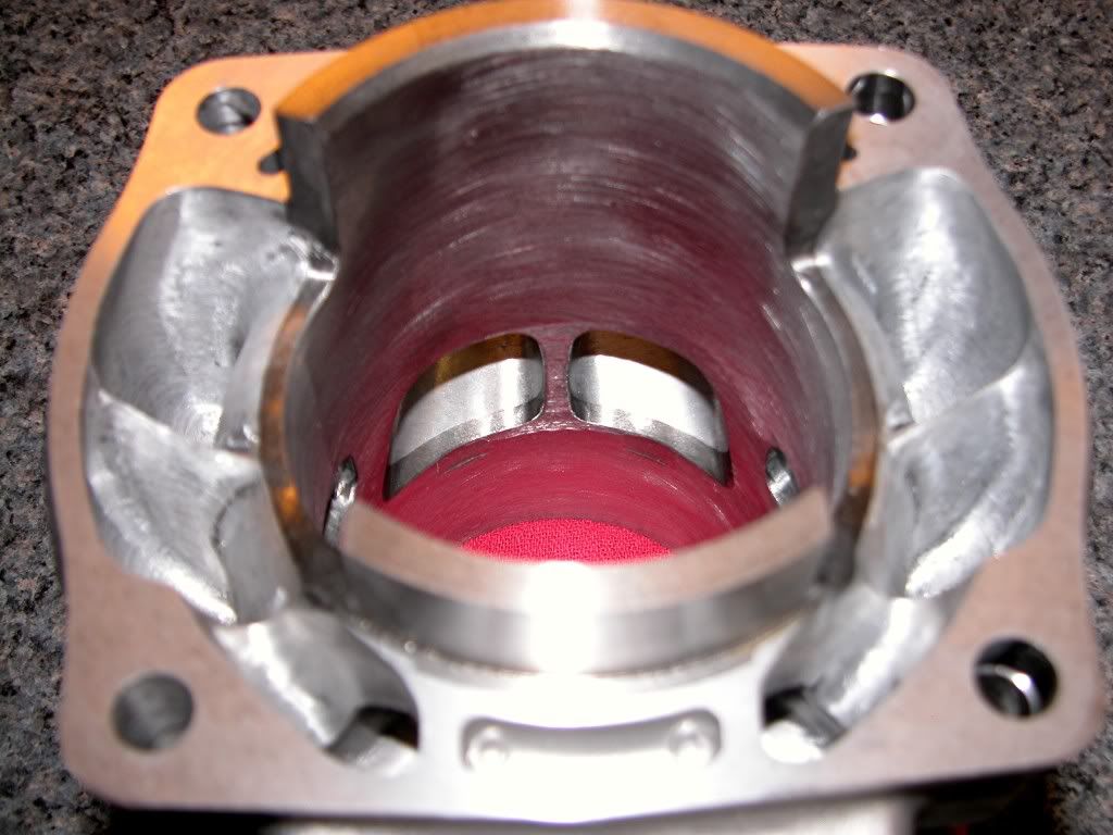
Matched and "smoothed" Exhaust port
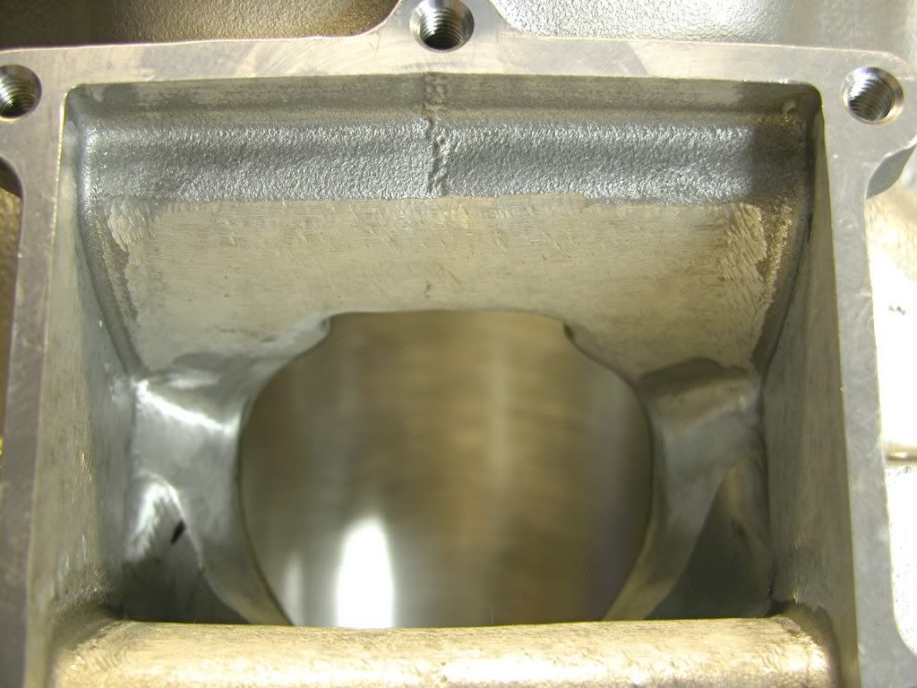
Matched and "smoothed" intake.
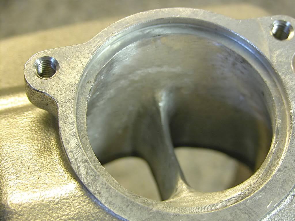
The base of the cylinder head was also machined to raise compression and a projected
nose spark plug is used.
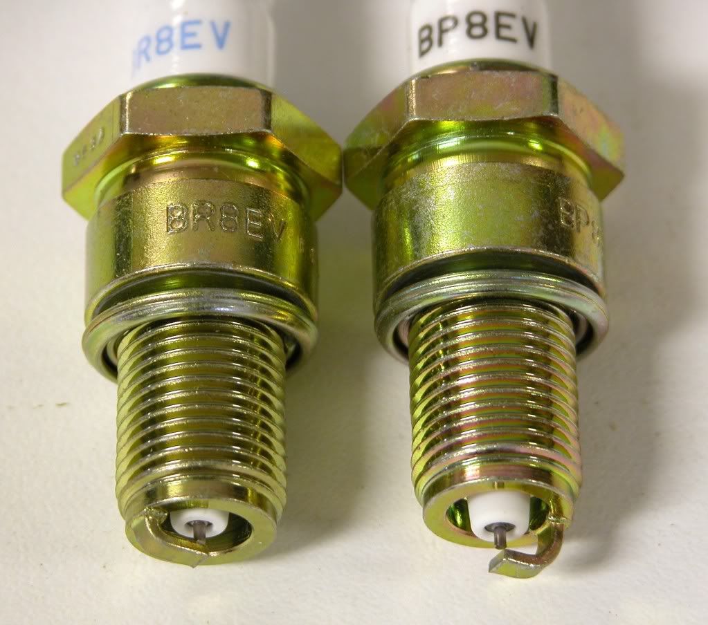
Comparrison of BR8EV (non-projected) on left to BP8EV (projected nose).
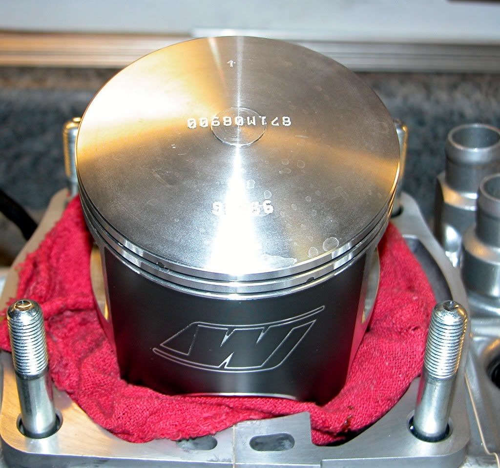
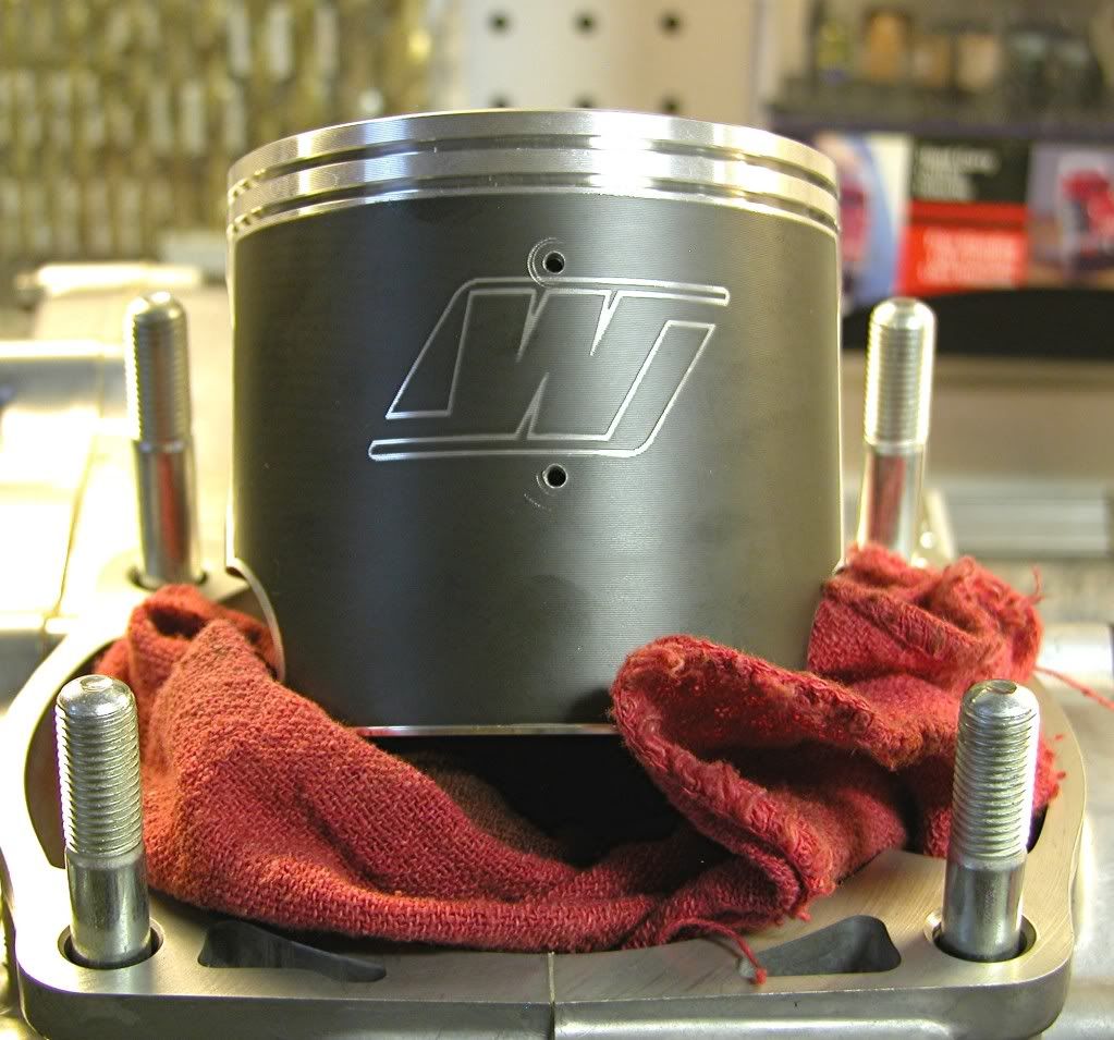
Piston selection is critical on a 500. The increased power and vibration take
a toll on the stock cast pistons. I like to use a forged Wiseco for this
application. This piston is very strong and comes with a nice slick coating
Wiseco calls Armorglide. The piston feature reliefs and lightening holes
to keep the weight down.
It's a good idea to thoroughly clean the freshly machined cylinder and head
to ensure that all debris has been removed. Next, wipe the bore down with
ATF and a clean cloth repeatedly until the cloth contains only clean ATF.
Now coat the bore with clean two stroke oil, it's ready to install.
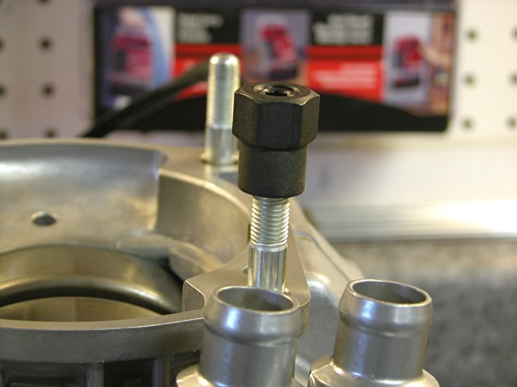
Prep the threads of the cylinder studs with Blue Loctite on the bottom and
anti-seize near the top of the threads and install with the rounded end of
the stud facing up using a stud installer or a pair of flange nuts. Torque to
25 lb.ft.
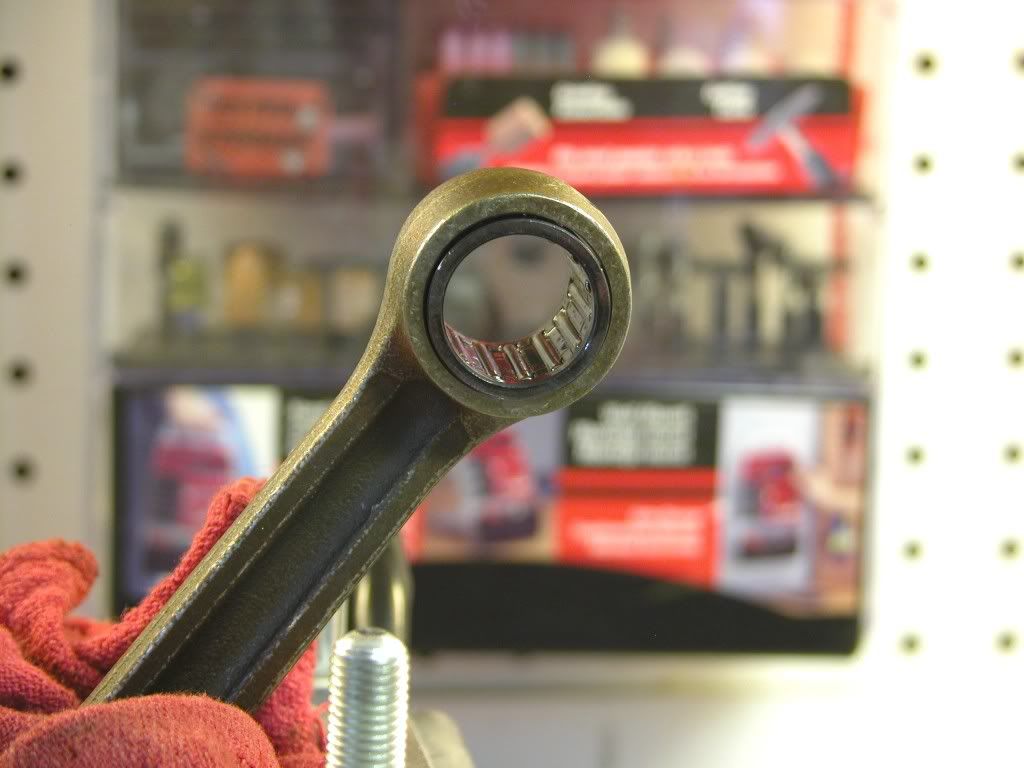
Coat the "small end" bearing with clean two stroke oil and install
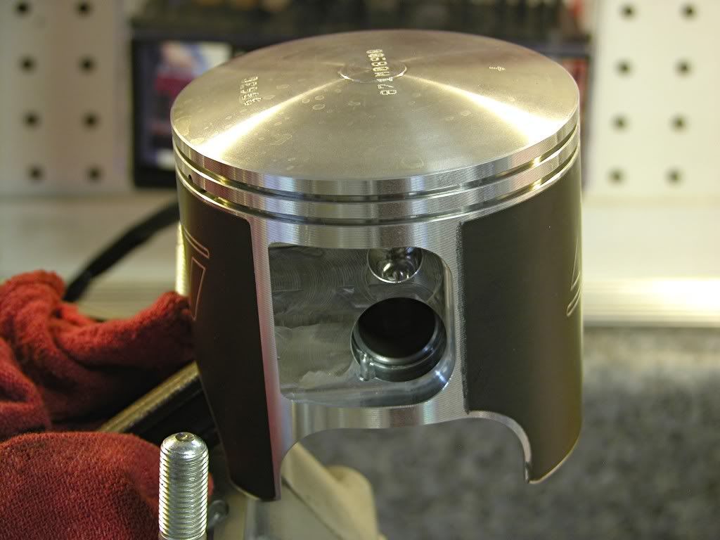
Install a new pin in the left side of the piston leaving the gap in the middle
clear. Place the piston over the rod and push the pin through. Install a
circlip into the groove on either side with the gap at the 12:00 or 6:00
position. Make sure the circlip is fully seated.
I'll finish the engine in the next segment.
dogger
installation.
The stock CR500 cylinder is unique in that it uses an unplated steel
sleeve.
This is what the cylinder looks like right out of the box. Note the sprayed on
plastic protective coating.
Since this engine is being built for MX racing, I decided to have it ported and
machined specifically for that purpose. The port work is designed to up the
power but smooth the "hit" making the bike faster but easier to ride.
Even though the cylinder is brand new, it was bored .001 over to ensure a
perfectly concentric bore. In addition to the port work, the base was
machined to lower the ports (alter the timing) and the intake inlet and
exhaust outlet were matched to the VForce and exhaust flange respectively.
Reworked inlet
Reworked exhaust ports
Matched and "smoothed" Exhaust port
Matched and "smoothed" intake.
The base of the cylinder head was also machined to raise compression and a projected
nose spark plug is used.
Comparrison of BR8EV (non-projected) on left to BP8EV (projected nose).
Piston selection is critical on a 500. The increased power and vibration take
a toll on the stock cast pistons. I like to use a forged Wiseco for this
application. This piston is very strong and comes with a nice slick coating
Wiseco calls Armorglide. The piston feature reliefs and lightening holes
to keep the weight down.
It's a good idea to thoroughly clean the freshly machined cylinder and head
to ensure that all debris has been removed. Next, wipe the bore down with
ATF and a clean cloth repeatedly until the cloth contains only clean ATF.
Now coat the bore with clean two stroke oil, it's ready to install.
Prep the threads of the cylinder studs with Blue Loctite on the bottom and
anti-seize near the top of the threads and install with the rounded end of
the stud facing up using a stud installer or a pair of flange nuts. Torque to
25 lb.ft.
Coat the "small end" bearing with clean two stroke oil and install
Install a new pin in the left side of the piston leaving the gap in the middle
clear. Place the piston over the rod and push the pin through. Install a
circlip into the groove on either side with the gap at the 12:00 or 6:00
position. Make sure the circlip is fully seated.
I'll finish the engine in the next segment.
dogger