Well, as it seems this request of help is doomed into oblivion, what I''ll try and do is, understand the functioning of the ICM (which fits the culprit role reasonably well) reverse engineering it, in an attemp to reproduce it with discret components.
I'm what you could call a noob as far as electrons are concerned, but I wont let this deter me (or, so I''ll try).
CDI of the era, (I will assume it's a CDI and not a TCI, but to be shure I'll have to carve into the original box itself) seem to employ an SCR to switch high currents and tensions, from the lower ones provided by the flywheel, to the HT coil, where the much sought after spark is provided.
Here the schematics of an SCR employed to switch on and off, like normal points would, and, to amplify, the current.
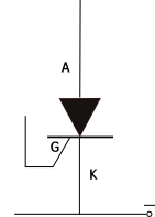
The current flow, from the anode A to the cathode K is controlled by the gate G which acts as a switch;
So, when we apply a tension to the gate, the junction between the latter and the cathode, becomes conductive and, current flows from A to K.
Once this happens, the SCR goes into a latching mode, meaning that it keeps conducting current until power is switched off.
Albeit this paper does not want to be academic for the shortcomings (of mine) pointed out, earlier, it will strive to be clear and concise and, above all adhere to the stark CR reality.
Enter two components of the CR combo : the PICKUP COIL and the KILL SWITCH.
We (didn't we?) said, the gate needs a tension of sort, in order to give the consent to the flow of current, from A to K and from K to the HT coil; what better then, that the signal from the
pickup coil (which is in tune, with the position of the piston, relative to TDC -Top Dead Center,- in actual fact starting to signal a few degrees before it -in our case 22* BTDC at 4000rpm-, so as to provide some opportune measure of advance)?
So, the signal from the
pick-up coil, very small in voltage (less than 10V) should be channelled and filtered for noise removal by respectively: a
diode, a
resistance and a
condenser (
capacitor), to the
gate of the
SCR.
Once becoming conductive in the
gate-cathode junction, the flow-path of the current, will be from the main
condenser to
ground, via the
SCR anode and
cathode and, from ground to the coil primary windings.
prolungare
In fact, the main
capacitor, will have in the meanwile been charged by the action of the kickstarter through the flyweel-exciter coil combination, which produces a tension in thsincronizzazionepe region of 100VAC converted to DC by a
diode before entering the
capacitor.
So, we introduced the pickup-coil, now, a brief explanation of the functions of the
kill-switch.
Please remember that I'm drawing from similar experiences, gathered from the net and from reverse (engineering) thinking.
The
SCR once triggered from the
gate voltage, goes into a latching mode, I.E. we could see current rushing from the anode to the cathode in a self sustained way, even after tension to the gate has been removed.
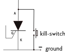
So, how do we stop the CR short of dropping fifth gear with no gas, brakes pulled?
I suppose we could use the kill-switch, wired in a way, inside the igniter, so as to short the A. more or less in this fashion:
But, prior to that, is more important to concentrate on how to synchronize the SCR. Currentrly. I am investigating the posasiibility of the ignition, supplying an alternating discharge tension, instead of the negative only one, supplied by the SCR.
Ideally, one ought to have a "twin spark" system, comprised of a point ignition, for the fatter spark that's able to supply on starting-up a cold engine, with the electronic one, kicking in, soon after the first spark, to prolong the latter, and have superior performance and better fuel efficiency at higher revs.
...
A degree of leniency is required of the reader, because of the steep angle, the learning curve is taking, at this stage.
Thanks
ADDENDUM
(last in first out)
inserted: (I will assume it's a CDI and not a TCI, but to be shure I'll have to carve into the original box itself)

