Another Algava Style Build

Building Tips, Suspension Set Ups, Conversion Parts .... Build to your Heart's Content!
Post Reply
User avatar
maddog1927
Posts: 313
Joined: April 4th, 2010, 8:10 am
Location: Mesa, AZ

Another Algava Style Build

Post by maddog1927 »

I had a CR250 frame laying around that I had got in a CL parts buy. The welds at the lower/back of the spar look as if someone has re-welded them. I am seeing weld on top of weld. I have no idea why that would be, nowhere else does it look re-welded, and I am not familiar with any cracking issues at this location. The lower tubes look like they have bottomed out more than typical, and the guy I bought it from had a FMX sticker in his window, so who knows. I'd love to hear your guys theories.

Image

Image

For more details on how to do this build see algava's post here:
http://cr500riders.com/cgi/yabb/YaBB.pl ... 913934/0#0

Also you may want to review my 125 build post, it goes over the Jig build, and other things guys interested in Gen 3 builds may find of interest.

http://www.bannedcr500riders.com/board/ ... hp?t=10808

More to come...
User avatar
maddog1927
Posts: 313
Joined: April 4th, 2010, 8:10 am
Location: Mesa, AZ

Post by maddog1927 »

For frame prep follow Algava's instructions. I used a portaband to cut the lower frame rails, just in front of the lower mount and a grinder to cut away the welds at the top of the wye, and the upper motor mounts. Cut most of the way through the welds, then try to pry the stuff off. On the motor mounts a Crecent wrench is your friend, cut most of the way through, then try to pry with the crecent, you'll know if you need to nibble more at the weld. The wye is a bit trickier, use a flat head screw driver, or sharp chisel to separate the wye from the main frame. I also drilled out the rivet that holds the wire connecter clip near the wye, and cut off the coil mounts. Clean up the frame as needed with a flapper wheel.

Image

Now its time to make lower frame inserts. Algava made his from 3/4" X 3/4" solid billet, and built up welds to flush out with the frame tubes. I made mine from 1" x 1" as to not need to build up as much weld.

I cut the square stock to length with a band saw, then squared the ends on a mill.
Image

Next made 1/8" deep cuts at the ends so the could insert into the lower frame tubes. I used a 45 deg. face cutter to leave a bevel for the weld.

Image

The one on the left is top view, the one on the right is side view. I made the spigot on the front shorter than the rear, you can't stick them in as far due to the curvature of the frame. Also notice the side view, the more nibbled side goes down and front, its cut more to accommodate the frame curve.

Image

I drilled 1/2" holes through the middle to allow for better heating during welding.

Image

I had to cut more from the top of the wye to get it to slide up far enough. It was hitting the radiator mounts.

Image

Also had to bevel the back of the frame down tube so the wye could pivot forward.

Image

I also had to bend the lower tubes in about 1/4" so they fit well on the extensions. I bent a little without the 2x4 spreader, then some with. I went little by little till I got it where I wanted it. you have to go a lot on the press, it springs back.

Image

With 59mm collar on the RH side and 54mm Collar on the LH side (125 spacers parts 5 and 6 on the 2002 cr125 parts breakdown for the swingarm. the Jig was not fitting well at the lower mounts. there was pressure on the RH mount. I test fit an engine to verify the jig was true, and same thing. I used a grinder, and took about the thickness of a cutting wheel .045" off, then it fit well and I used a washer for the LH side.

Image

I also had to file the lower LH motor mount hole forward a tad.

Image

Now time to mod the upper motor mounts.

Image

I did a bit at a time and test fit till they were just right.

Image

My spacers lengthened the cradle 26mm

Image

I bead blasted what I could and sanded what I couldn't to have clean for welding.
User avatar
AlisoBob
"Hoon-father"
Posts: 15404
Joined: May 31st, 2007, 6:39 pm
Location: Aliso Viejo Ca

Post by AlisoBob »

maddog1927 wrote: I also had to file the lower LH motor mount hole forward a tad.

Image
When you get it welded and all together, match drill all the holes for 11mm - 7/16" hardware for a perfect fit.

:wink:
User avatar
maddog1927
Posts: 313
Joined: April 4th, 2010, 8:10 am
Location: Mesa, AZ

Post by maddog1927 »

Need to Grind down the OEM weld at the RH rear cradle, case hits...they all do at this location on the gen 3...easy fix.

Image

Good exhaust clearance:
Image

Good water pump clearance

Image

I live my life on the "ragged edge" Despite only having welded about 4.75 linear inches of aluminum before in my life, and having limited TIG experience... I did my own welding. Feel free to give pointers, and honest opinions, won't hurt my feelings at all. I used a rose bud to preheat, particularly at the Billet inserts, per MX dodgger???s recommendation.

Image

Image

Image
User avatar
bearorso
Posts: 300
Joined: February 28th, 2009, 10:59 am

Post by bearorso »

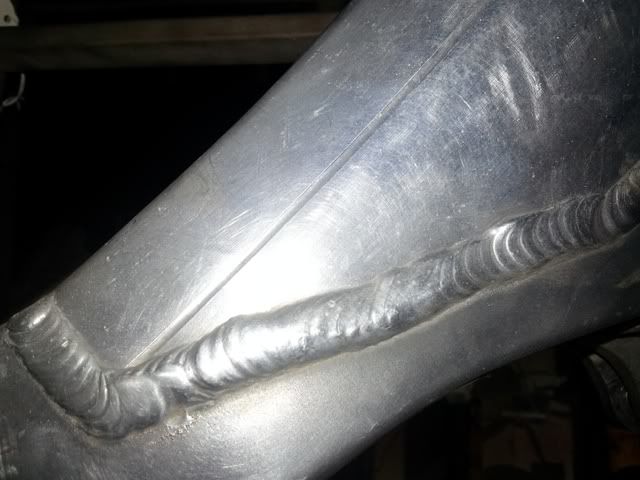
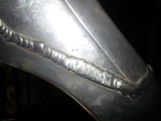
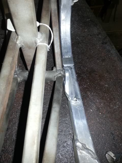
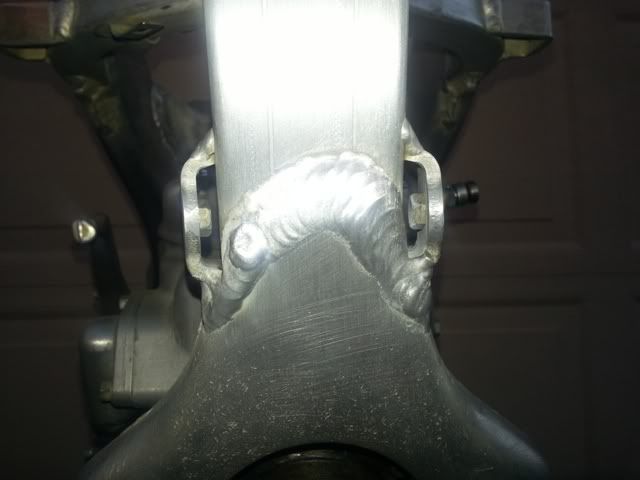
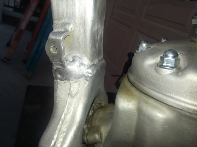
All things considered, your welds are not too bad / fairly good. Some sections with low amps / some with too high - you can see where your welding speed / amperage used did not match, notably on the front of Y / Downtube. It looks like it 'got away from you', but you handled that relatively well, picking up on your wire feed and pace.

You've done far better than many welders I've seen on AFs - even better than a "certified aircraft welders" work I've seen here. :shock: :lol:

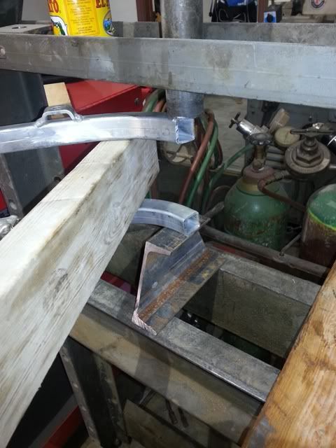
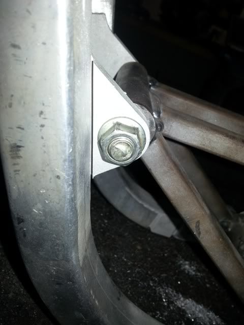
I'd highly recommend you 'roundel / diamond / tarpaulin' reinforce both the front and rear of the Y / downtube junction. Try not to place a weld across the horizontal faces of the downtube (if your using a 'tarpaulin' - rectangular plate), as it just introduces another haze zone, and a high stress line right across the DT. Make sure you 'button' any craters at the weld finish points - and / or make the finish points down on the Y's faces.

As for pre-heating - unless your using a low power welder, it's complete and utter Bull Shit. Nothing on an AF is a heavy enough section to require it, and you're only extending the HAZE Zone. But, I'm 52, and have only tig'd since I was about 13 yrs of age - what would I know?

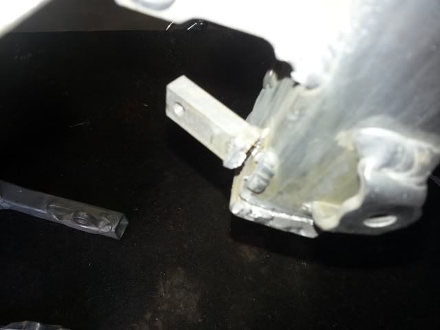
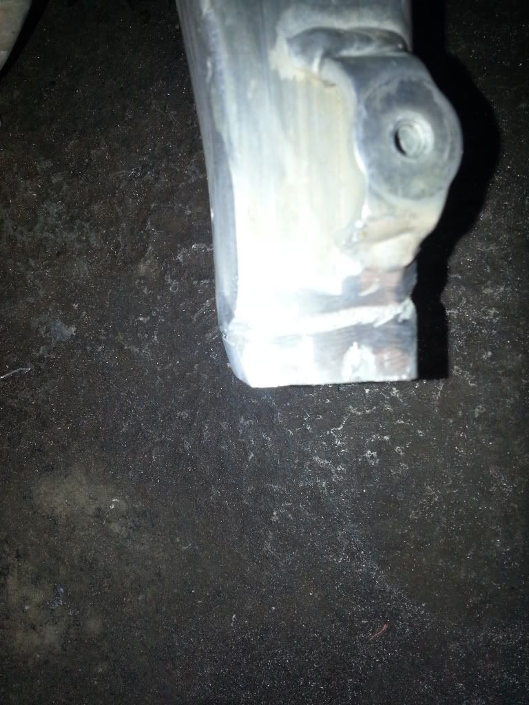
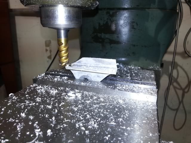
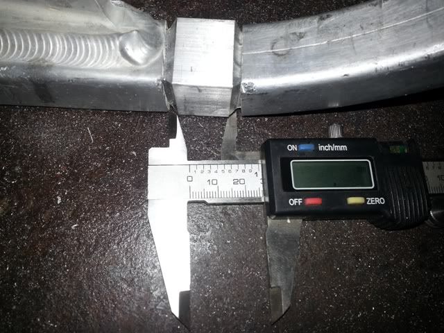
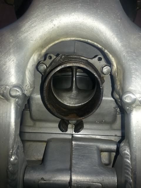
Did you 'rossette / button' weld the male sections of the inserts, to the original cradle tubes? I hate the insert method, but, done well, with good engine mounts done, and the Y / DT done well, you rarely have problems with them. They certainly are a much quicker thing than a whole new cradle, but that's the very best way to do things - a whole new cradle. Doing new 'middle mounts', that extend over the inserts weld joints, pretty much guarantees no problems. Your hollowing of the inserts, actually made them stronger / safer than if you'd left it 'solid'. Well done.


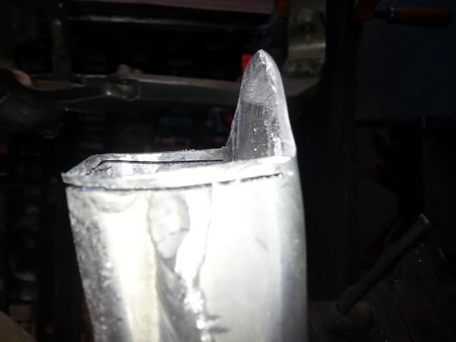
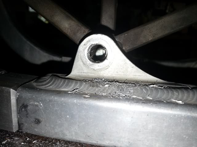
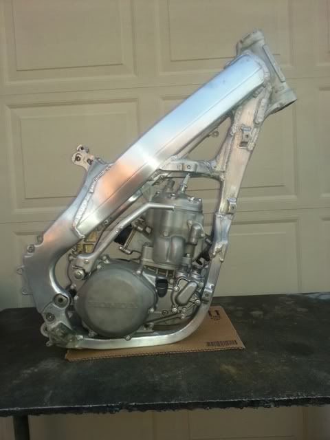
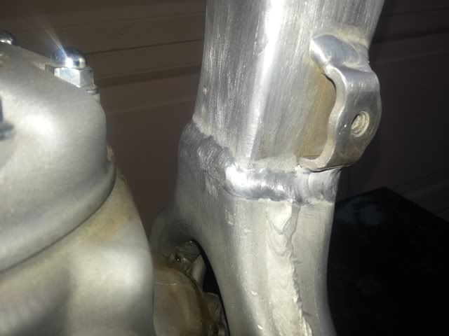
Now, here's the One, Big Worry I have for this build. That those welds at the outer tower / spar junction have been gone over, may indicate that frame has been hammered within an inch of it's life. Aluminium, really, Really, REALLY has a finite stress cycle life. It's something All should be aware of.

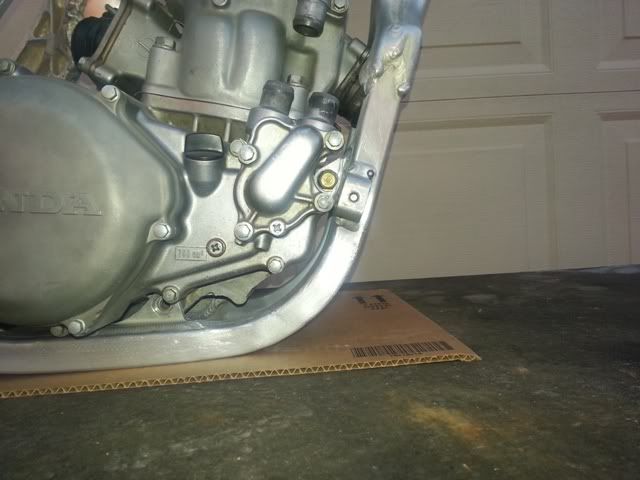
But, they are strange areas for a weld to have started to fail. "Egging" of an AF frame - as they are meant to do, the spars flexing outwards from high forces - tends to crack the spars, just at, or very slightly forward, of the shock tower / inner spar weld interface, hence the welded cracks you'll see at times, inside, then going across the tops, then onto the outer upper sides of spars - especially on HC bikes, with the massive loads put into the frame from the long swingarms, and big frontal impacts. I've gone into that here, a few years ago, I think.


I HAVE seen frames with welds like that, on brand new bikes, years ago. If your lucky, it might be that type of thing - not so pretty, 'at factory' rectifications of a incomplete / faulty weld that is discovered during QC inspections. But, if it isn't that, you may have a frame, that you want to be Very Careful about. It may just have had such a pounding, that much of the frame, is past it's service life.

Think about your safety, always.
mocr13
Posts: 54
Joined: November 20th, 2009, 7:08 am

Post by mocr13 »

just a idea, im nobody but wonder if freestyle guy had frame welded extra to try and avoid damage later from repeated hard hits? just a theory?
User avatar
Gmbond
Posts: 381
Joined: September 14th, 2009, 7:17 pm
Location: Ontario Canada

Post by Gmbond »

I am thinking it may just be ugly OEM welds

My 2003's have some less than pretty welds in different spots
tvalliere27
Posts: 16
Joined: December 16th, 2012, 9:22 am

Post by tvalliere27 »

maybe it was a frame they tested weld settings on before producing them :roll: :roll: :roll: :lol: :lol: :lol:
cryzsurfer
Posts: 91
Joined: December 28th, 2008, 12:16 pm

Another Algava Style Build

Post by cryzsurfer »

I think it's a factory weld. If you look closely you can see where there's some of the MIG weld showing and they just sweated over it with GTAW for cosmetic purposes. They use GMAW and GTAW on the frames with the wire feed in the places out of normal sight. They usually use GTAW on the wraps and the stuff out in the open. I wouldn't worry about it as it was possibly after lunch and the welder may have stepped out and burned a big fat one or drank a few beers.
Craigus
Post Reply