Gen 4 crf450 flat sheet "Y"
-
Roostius_Maximus

- Site Admin
- Posts: 4641
- Joined: November 16th, 2007, 3:24 pm
- Location: Mt Nebo, Manitoba, Canada
- Contact:
what dimensions on the sheet?
http://www.youtube.com/user/500bigbore
My CR500 Tech Reference... http://sdrv.ms/1a0CIiz
MRE Components... http://sdrv.ms/1bs2zhd

My CR500 Tech Reference... http://sdrv.ms/1a0CIiz
MRE Components... http://sdrv.ms/1bs2zhd
-
cr500binks
- Posts: 55
- Joined: April 12th, 2010, 7:54 am
- Location: cornwall, UK
- Contact:
thanks for the reply guys. i didnt think about using the 7 series alloy but im pretty sure ive seen that stuff about in the uk. ad i like the thought of using different thickness alloy when making the "y" section. as for the sheet size i think 1mx1m would be mre than enough !
if it dont smoke its a joke
-
cr500binks
- Posts: 55
- Joined: April 12th, 2010, 7:54 am
- Location: cornwall, UK
- Contact:
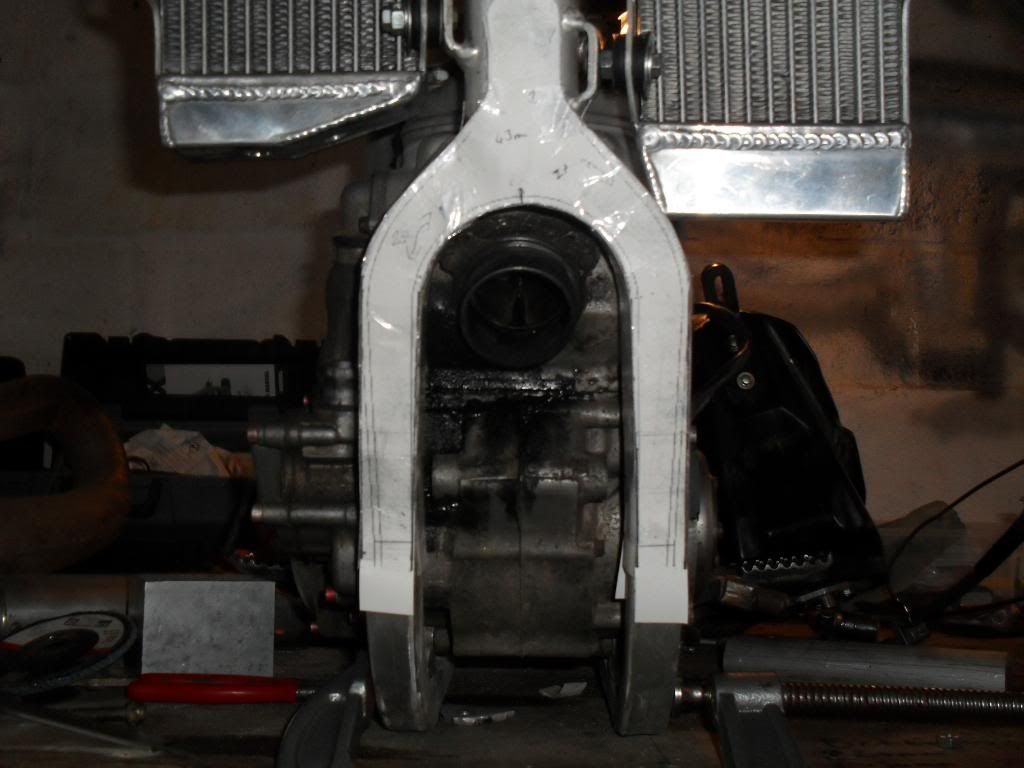
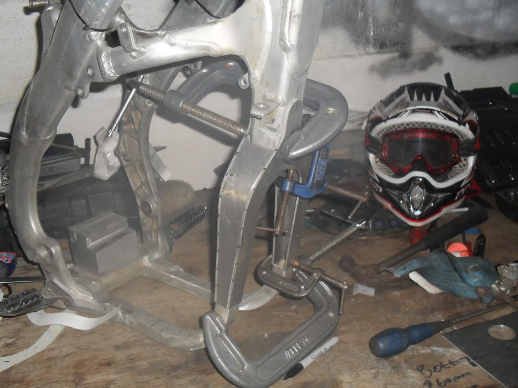
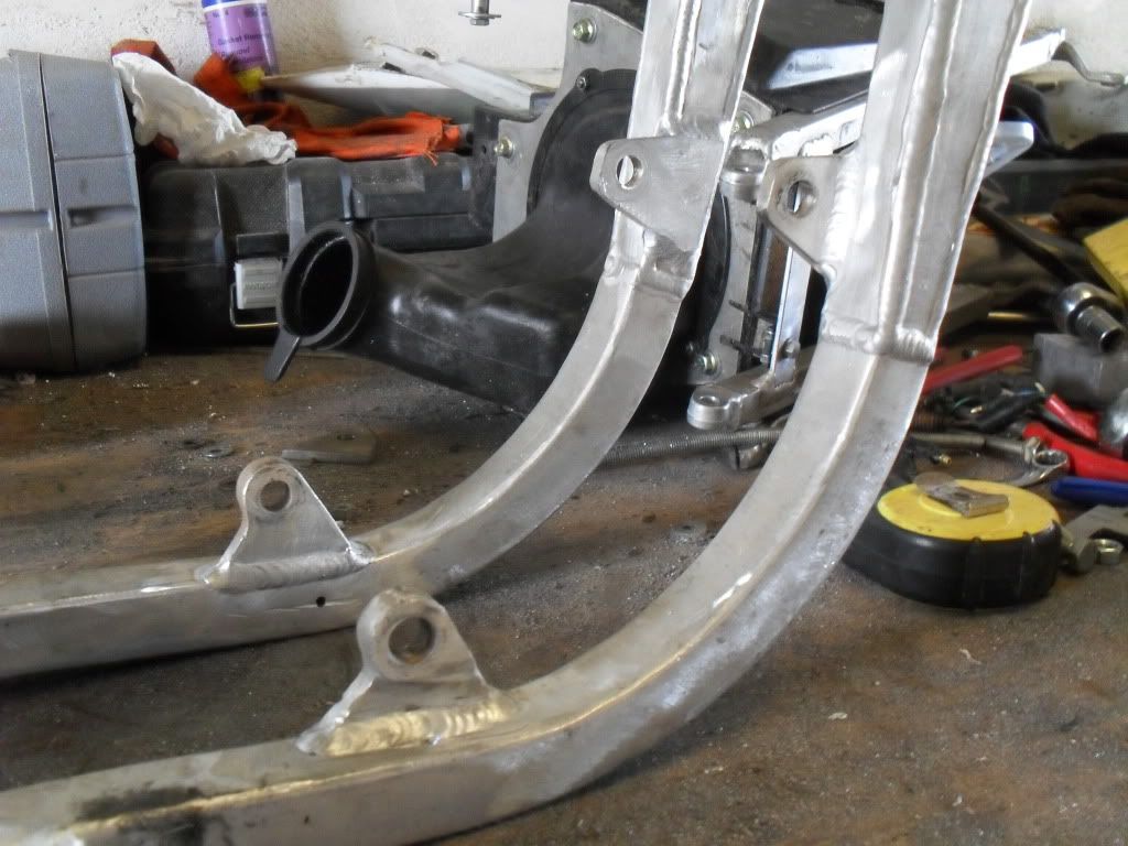
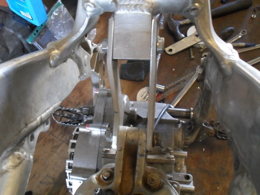
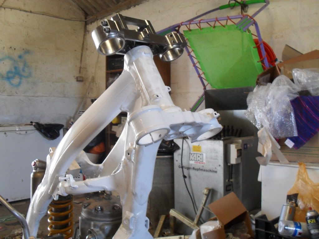
just a bit of an update, ive had abit of time off work so i got all the alloy i needed and have started making the "Y" section, i have also made a head stay which i will have welded to the frame by the top of the shock mount. here's some pics.....
Last edited by cr500binks on October 17th, 2011, 3:27 pm, edited 1 time in total.
if it dont smoke its a joke
-
cr500binks
- Posts: 55
- Joined: April 12th, 2010, 7:54 am
- Location: cornwall, UK
- Contact:
just a bit of an up date,
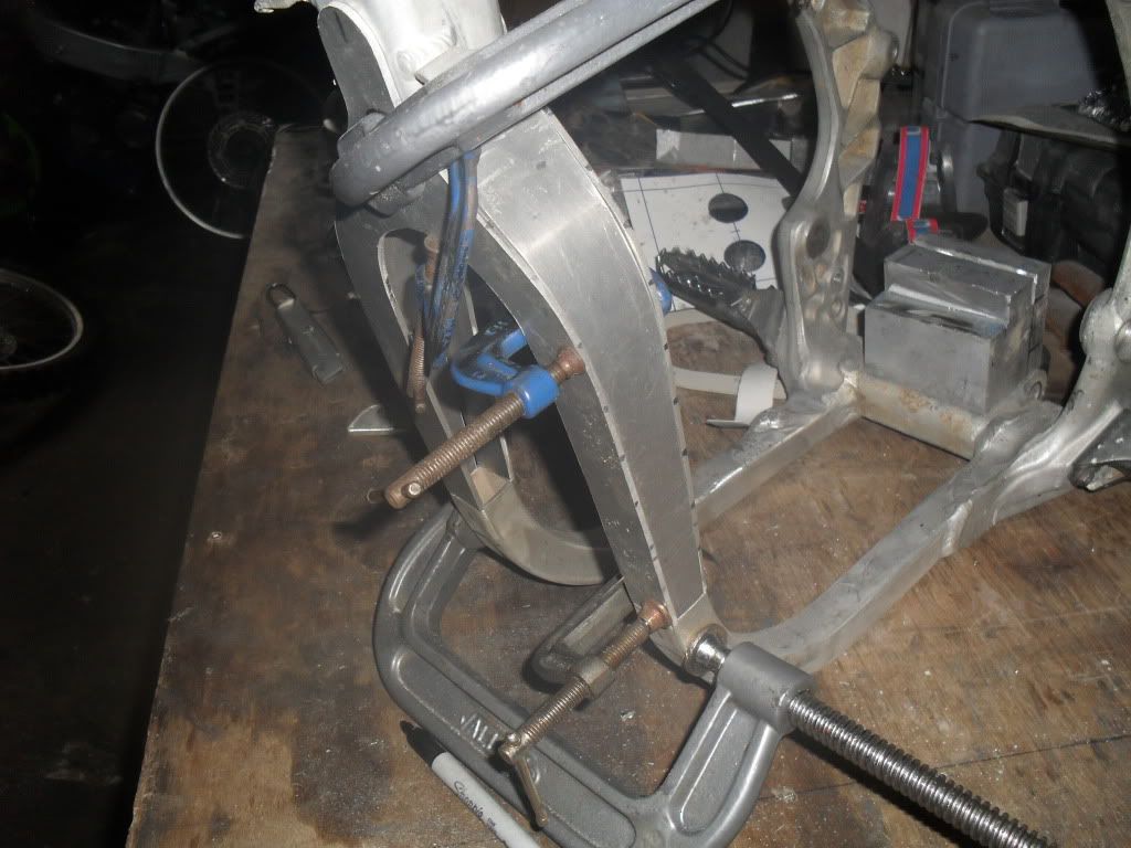
i made up the new "Y" section out of the alloy and have dropped the frame off for some welding. the guy who is welding it used to be in the royal navy making planes and helicopters for 20 years and now he owns his own shop, he said it would be done by the end of the week but it would probally make it to his bench sooner cos hes very intrested in it ! he was also talking about heat treating and im just wondering what are peoples views on it ??
some pics.............
if it dont smoke its a joke
I love plated Y's, it's my build of preference (even moreso, fully plated cradles, but they are an enormous amount of work - but a full plated cradle / Y combo is easily 'heat treated' prior to attaching to the down-tube and SA castings). It gives you enormous amount of dimensional and material guage options. I know a lot of frame makers in the UK use 7020 extensively - it's a great material.
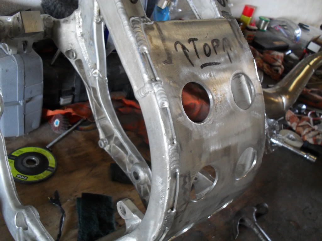
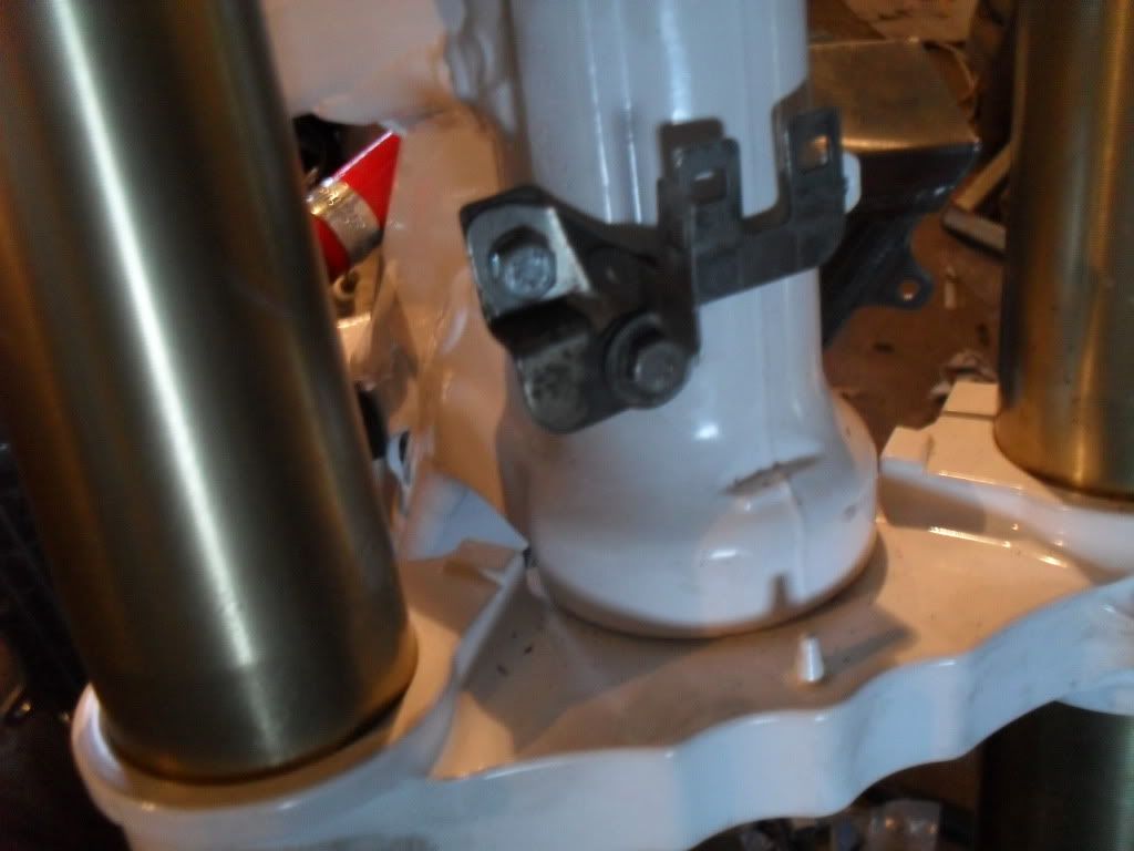
I'm concerned that you might be relying on just butt welds at the cradle , Y joint. With the inner plate not in the picture, perhaps you are placing a shaped plug bar into the Y and cradle, for rosette welding, or you are going to have the inner plate lapping over the existing railings?
Here's an idea, if you have not thought of this yourself :
Make the front engine mount plates quite long, crossing the butt weld joint that I see here. Resist the temptation to weld across the inner side of the Y plates, and the inner side of the original cradle - Weld only on the long radius edge, and the short radius edge, and that edge only at the start and finish of the plate - no weld (say, a third of the plate length) near the engine mount bolt area. This is what I do at plated Y and original cradle joints. I've also done a couple with removable engine mount plates - as in the plates bolt to the plate welded to the Y and cradle, then the engine. I did this with 2 mates Gen 5 bikes recently - one with the plate / engine interface direct, one with the plate, mount plate, engine mount interface.
These blokes are fellows I've worked with over the years on other projects, both very competent riders, both who I know I can rely on for good, Real feed back - or that I can sort out / understand from knowing them so long.
Both preferred the bolt in plate mount. And we experimented with different plates - one preferred 4130 plate, the other preferred 4.8mm 6061. I made the frame that originally had a direct mount / engine interface so I could easily convert it to the mount plate type, as I was fairly sure that was going to be what they both preferred.
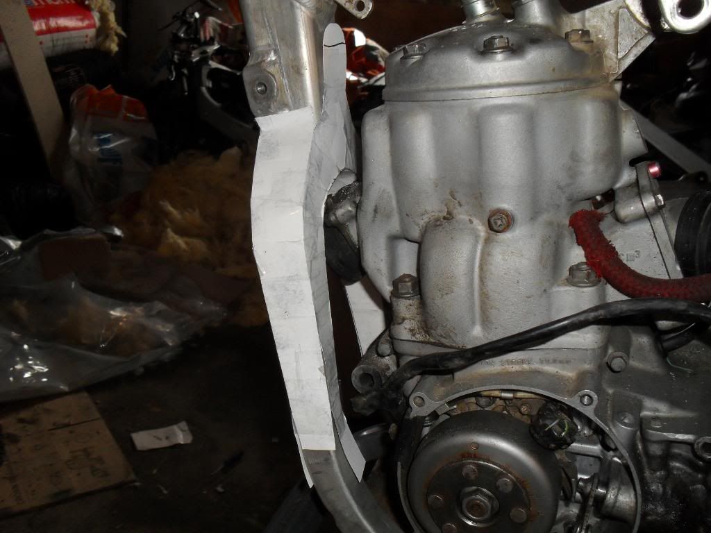
With your top mount, I'd weld a pad onto the the shock cross over tower, both because that frame does not have a head stay originally attached to it, and the small size of the head stay mount interface you've made.
I'd recommend you do something about the sharp inside corner of the head stay mount you've made - there's a stress raiser that could cause you a bit of grief. You can use the mount you've done still, as an 'inner' radius (drilling / milling a inward radius into a corner) is quite a common stress relieving engineering process.
Heat Treating is a very sweeping term - it can cover the full range of solution heat treating, to some drongo passing a flame over the weld joint. The Only form of 'heat treating' I'd subject AF frames to is that of artificial aging, in it's simpler forms, as the frames are a mixture of a 7000 series (I'd say a mix that is proprietary to Honda), and 6000 series materials. 7000 series does not take kindly to post weld heat treating. The bloke here that I'd defer to is Cryzsurfer (?), as metal treatment is what it appears he is working in. There's no guessing / assuming with his posts.
I'm concerned that you might be relying on just butt welds at the cradle , Y joint. With the inner plate not in the picture, perhaps you are placing a shaped plug bar into the Y and cradle, for rosette welding, or you are going to have the inner plate lapping over the existing railings?
Here's an idea, if you have not thought of this yourself :
Make the front engine mount plates quite long, crossing the butt weld joint that I see here. Resist the temptation to weld across the inner side of the Y plates, and the inner side of the original cradle - Weld only on the long radius edge, and the short radius edge, and that edge only at the start and finish of the plate - no weld (say, a third of the plate length) near the engine mount bolt area. This is what I do at plated Y and original cradle joints. I've also done a couple with removable engine mount plates - as in the plates bolt to the plate welded to the Y and cradle, then the engine. I did this with 2 mates Gen 5 bikes recently - one with the plate / engine interface direct, one with the plate, mount plate, engine mount interface.
These blokes are fellows I've worked with over the years on other projects, both very competent riders, both who I know I can rely on for good, Real feed back - or that I can sort out / understand from knowing them so long.
Both preferred the bolt in plate mount. And we experimented with different plates - one preferred 4130 plate, the other preferred 4.8mm 6061. I made the frame that originally had a direct mount / engine interface so I could easily convert it to the mount plate type, as I was fairly sure that was going to be what they both preferred.
With your top mount, I'd weld a pad onto the the shock cross over tower, both because that frame does not have a head stay originally attached to it, and the small size of the head stay mount interface you've made.
I'd recommend you do something about the sharp inside corner of the head stay mount you've made - there's a stress raiser that could cause you a bit of grief. You can use the mount you've done still, as an 'inner' radius (drilling / milling a inward radius into a corner) is quite a common stress relieving engineering process.
Heat Treating is a very sweeping term - it can cover the full range of solution heat treating, to some drongo passing a flame over the weld joint. The Only form of 'heat treating' I'd subject AF frames to is that of artificial aging, in it's simpler forms, as the frames are a mixture of a 7000 series (I'd say a mix that is proprietary to Honda), and 6000 series materials. 7000 series does not take kindly to post weld heat treating. The bloke here that I'd defer to is Cryzsurfer (?), as metal treatment is what it appears he is working in. There's no guessing / assuming with his posts.
-
2t500nutter

- Posts: 11
- Joined: February 16th, 2011, 11:12 am
- Location: Lake Macquarie NSW Australia
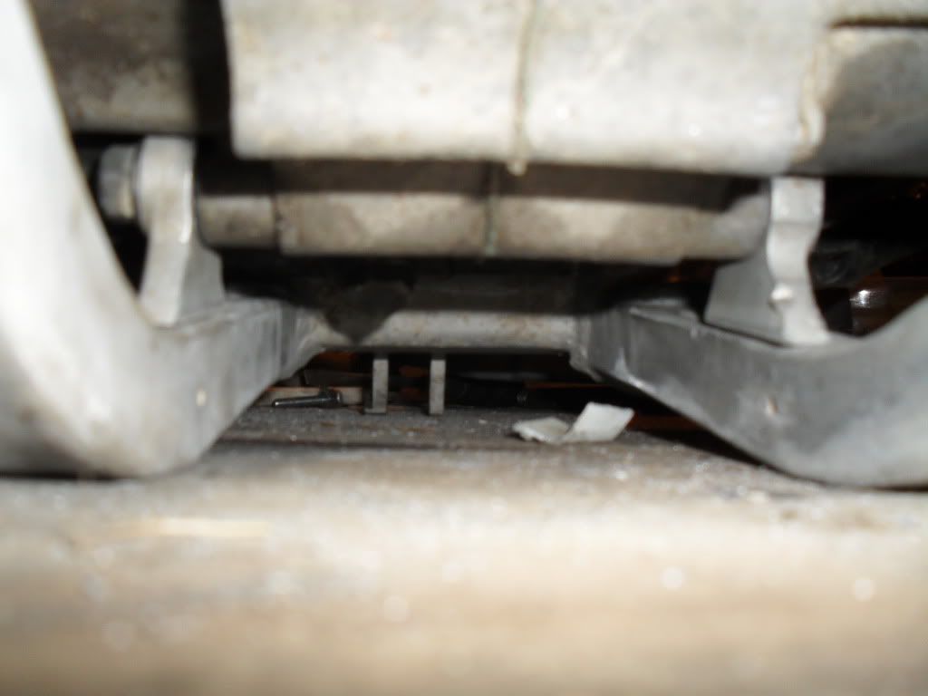
I just started an aluminium welding business & I've done 3 af conversions now.. I ran mine for a year to see if it had any problems.. I use the 125 frame, cut the headstay, bottom frame rails & Y piece off first.. The headstay is welded back on the frame after the swingarm mount is aligned correctly.. 125 swingarm spacers are the perfect size & usually don't need any machining.. then I line up the airbox to carb connection, the original Y piece is ok to use after moving it up to clear the exhaust port (give yourself enough room to get the pipe on & off, my first af was way too close..) The frame rails are rolled into shape using a section roller & are replaced in one piece from the Y to footpeg mount.. Then I make brackets for the bottom 2 engine mount holes.. One question I keep getting asked is why do some af's crack at the Y piece.. It's the torque from the 500.. Some converters don't realise how the swingarm mounting point & headstay are the most important mounts on the big engines, (under acceleration the motor tries to rock back, the mounts under the engine only have a 6mm bolt & are only on a 1 inch square tube.. So they can't hold the torque, they flex & cracks appear at the front of the frame..) A BIG BEEFY HEADSTOCK MOUNT IS UNDER THE SEAT TO STOP THAT, SO DON'T GO HALF ASSED ON THAT MOUNT.. Do a 125 frame , leave the 125 stickers on it & watch the 450 4stroke boys shit themselves when you fly past in a shower of rocks.. it's funny..

-
cr500binks
- Posts: 55
- Joined: April 12th, 2010, 7:54 am
- Location: cornwall, UK
- Contact:
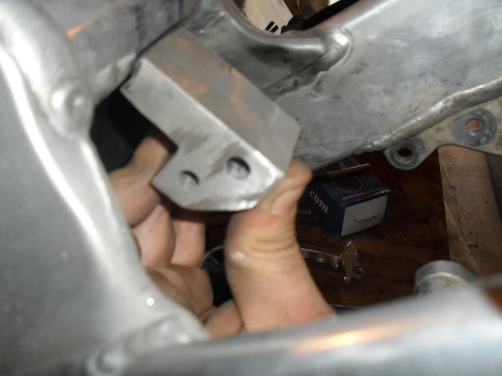
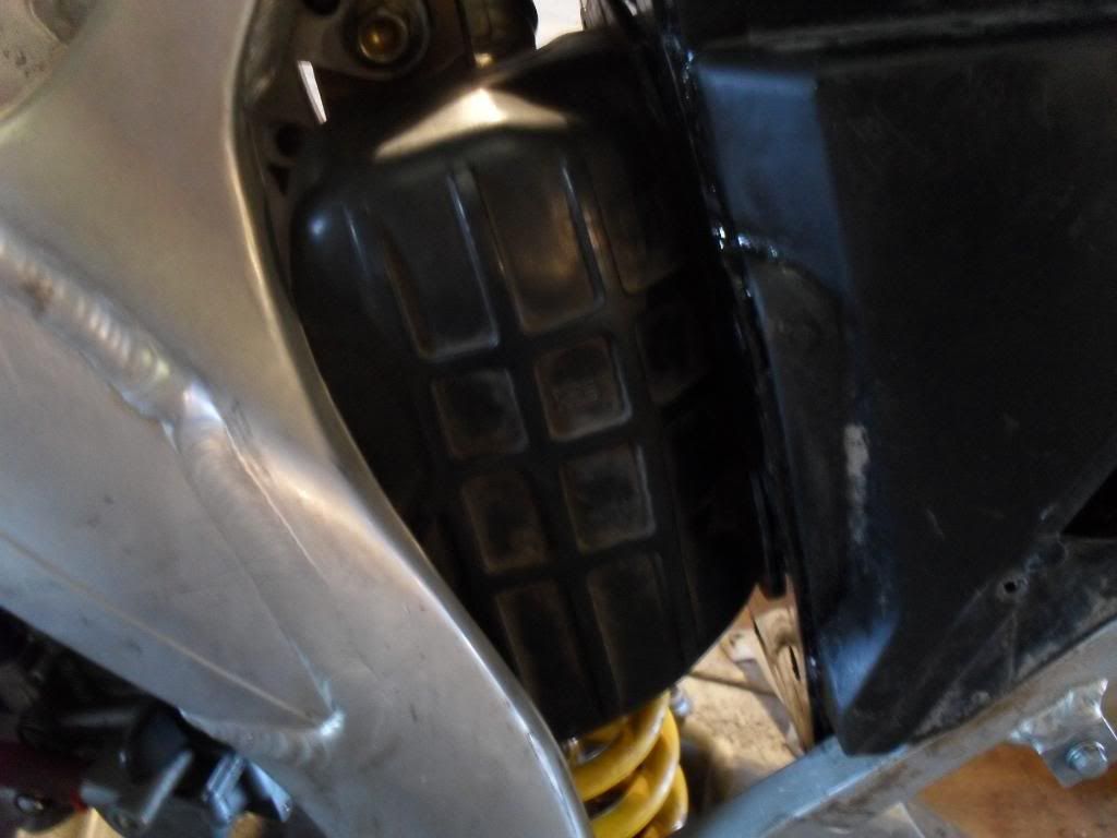
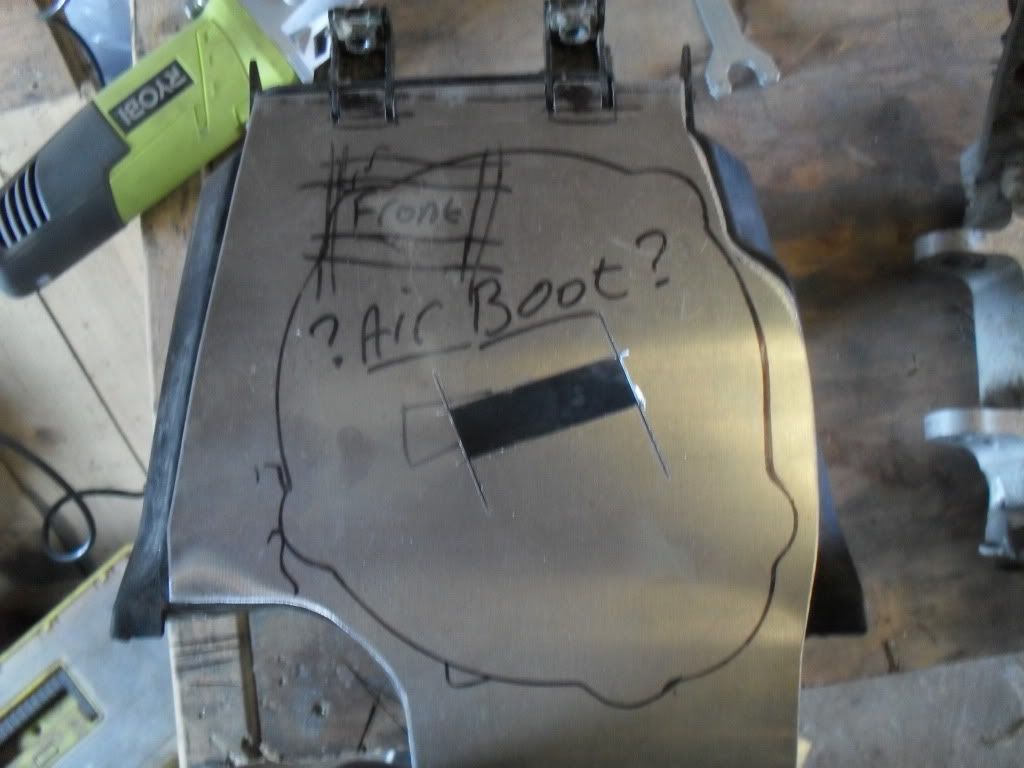
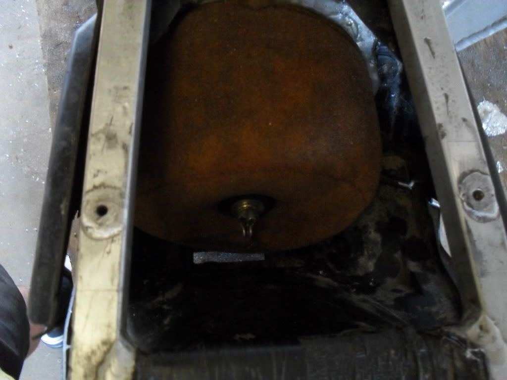
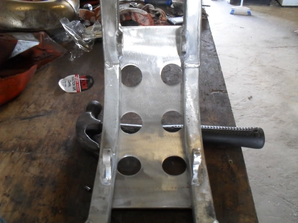
just a bit o an update, i got the engine mounts all welded in and i have done a new head stay which had been tacked into place. i also made a new air box spacer out of alloy as i wasnt keen on the plastic one.
[/img]http://s367.photobucket.com/albums/oo11 ... 84.jpg[img]
[/img]http://s367.photobucket.com/albums/oo11 ... 23.jpg[img]
[/img]http://s367.photobucket.com/albums/oo11 ... 90.jpg[img]
for the air box i used a 1998 cr250 air boot and my cr500 filter and it all fits together good. im going to have a frame/sump guard welded to the frame which will over lap the butt joins of the "Y" section which will give it extra strength.
[/img]
if it dont smoke its a joke
-
cr500binks
- Posts: 55
- Joined: April 12th, 2010, 7:54 am
- Location: cornwall, UK
- Contact:

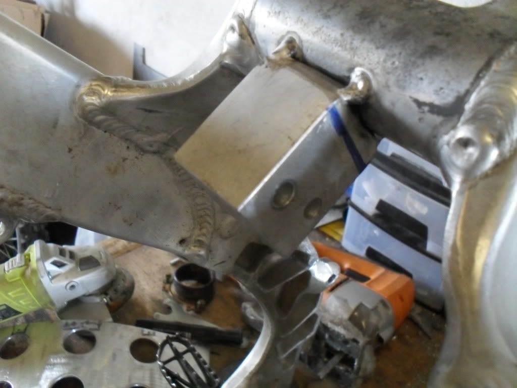
looks like the mounts could be made better i dont think the bottom wiil last not much their hate to see them mounts destroy all the work you put into the y also i used lexan on the box has worked without problems cost 5 bucks and way easy to work with paint backside black and rivit it can hardly tell its been modded
no wing no prayer
-
Flatbiller
- Posts: 125
- Joined: January 22nd, 2011, 1:10 am
- Location: Las Vegas


-
cr500binks
- Posts: 55
- Joined: April 12th, 2010, 7:54 am
- Location: cornwall, UK
- Contact:
im pretty sure the mounts will be fine ! the "Y" section is butt welded but the frame/sump guard i got is going to be welded to the frame and it will also cover the butt joints and strengthen them up. i also changed the headstay its a 1.5" square bar with one end shaped to fit the shock top mount.
[img]<a href="http://s367.photobucket.com/albums/oo11 ... t=0242.jpg" target="_blank"><img src="http://i367.photobucket.com/albums/oo11 ... t/0242.jpg" border="0" alt="Photobucket"></a>[/img]
[img]<a href="http://s367.photobucket.com/albums/oo11 ... t=0213.jpg" target="_blank"><img src="http://i367.photobucket.com/albums/oo11 ... t/0213.jpg" border="0" alt="Photobucket"></a>[/img]
[img]<a href="http://s367.photobucket.com/albums/oo11 ... t=0193.jpg" target="_blank"><img src="http://i367.photobucket.com/albums/oo11 ... t/0193.jpg" border="0" alt="Photobucket"></a>[/img]
if it dont smoke its a joke
-
cr500binks
- Posts: 55
- Joined: April 12th, 2010, 7:54 am
- Location: cornwall, UK
- Contact:
-
cr500binks
- Posts: 55
- Joined: April 12th, 2010, 7:54 am
- Location: cornwall, UK
- Contact:
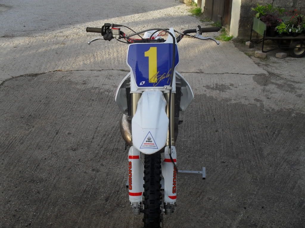
i got these back from powder coating on saterday

then this happened


i used a crf250 cdi mounting bracket and rubber sleeve to tuck the cdi behind the number plate
the front pipe mounts on all of its orignal moun6ting points and brackets, it looks good and i have plenty of clearence to the front wheel.
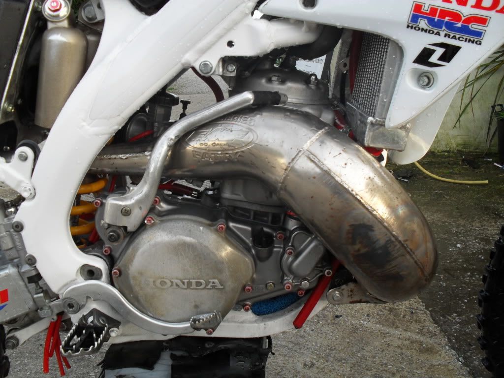
i cut the pipe from the silencer rotated it and welded it up. it gives good clearence from the back wheel and sits on the rubber gromet in the panel. i dont like the look when the silencer sits away from the side panel.
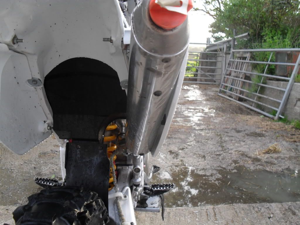
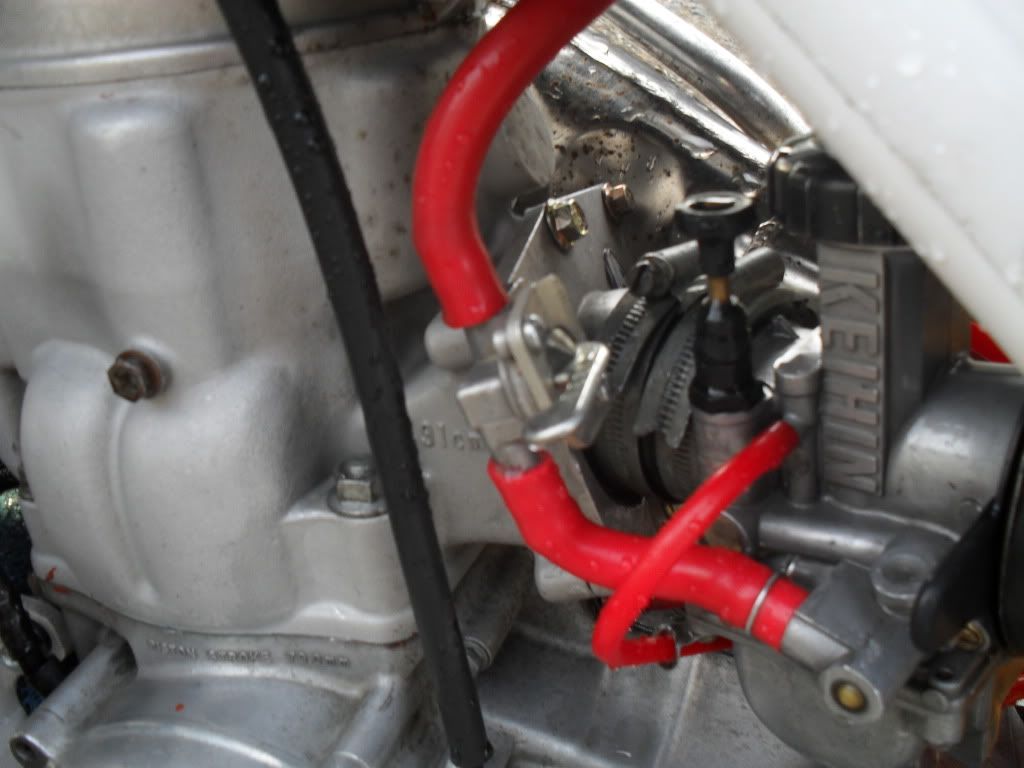
i mounted the fuel tap on the reed block because i turned the outlet on the tank around to clear the spark plug and if i had the tap in its orignal place the hose would kink.
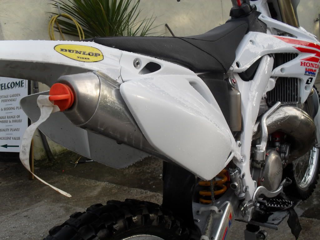
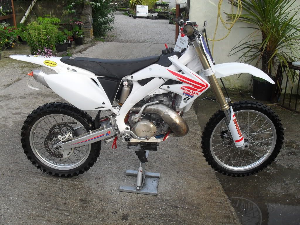
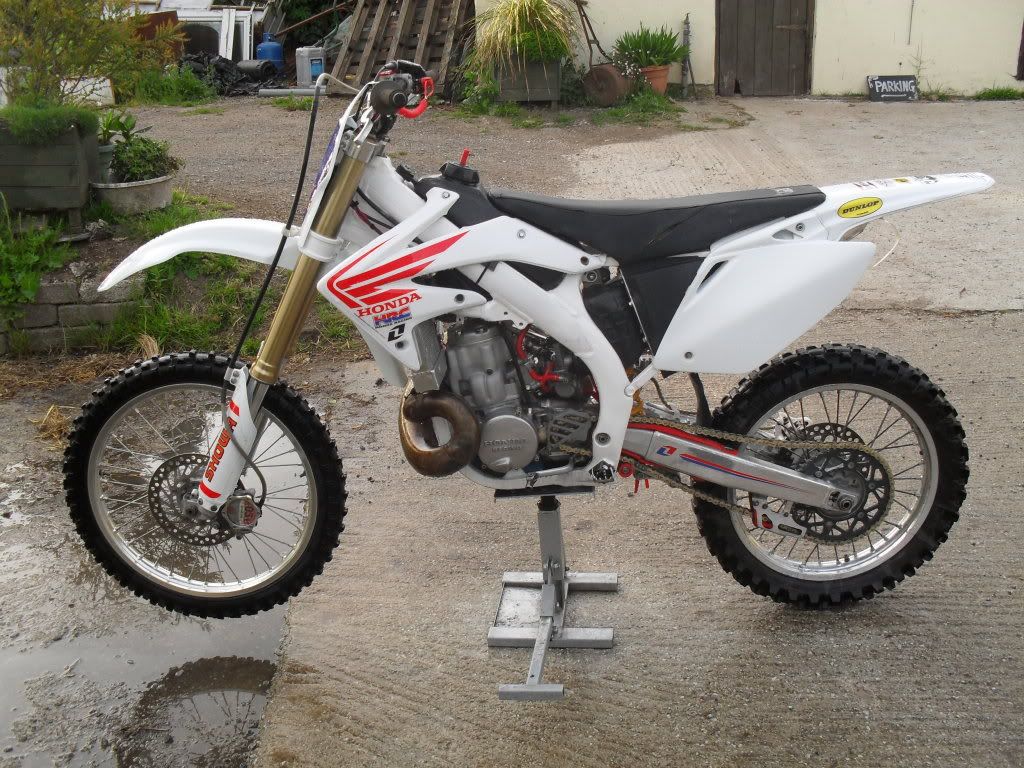
i also got some new plastics and some bailey graphics
then this happened
i used a crf250 cdi mounting bracket and rubber sleeve to tuck the cdi behind the number plate
the front pipe mounts on all of its orignal moun6ting points and brackets, it looks good and i have plenty of clearence to the front wheel.
i cut the pipe from the silencer rotated it and welded it up. it gives good clearence from the back wheel and sits on the rubber gromet in the panel. i dont like the look when the silencer sits away from the side panel.
i mounted the fuel tap on the reed block because i turned the outlet on the tank around to clear the spark plug and if i had the tap in its orignal place the hose would kink.
i also got some new plastics and some bailey graphics
Last edited by cr500binks on May 29th, 2011, 3:47 pm, edited 3 times in total.
if it dont smoke its a joke
-
cr500binks
- Posts: 55
- Joined: April 12th, 2010, 7:54 am
- Location: cornwall, UK
- Contact:
well boys and girls i have used the bike quite a bit and i frickin love it, and i started wondering why i didnt do it sooner ??? the handling is amazing and its just awesome to ride ! no problems with it yet and the engine mountsare holding out very well i do regular checks on the "Y" section and its all seeming good !
i have also just got myself a gen 3 450 frame and another cr500 engine so im ready to do it all again, im just wondering weather or not to go the flat sheet "Y" route again as i personaly think its the stronger option ! i will start my gen 3 build thread soon so watch this space !
i have also just got myself a gen 3 450 frame and another cr500 engine so im ready to do it all again, im just wondering weather or not to go the flat sheet "Y" route again as i personaly think its the stronger option ! i will start my gen 3 build thread soon so watch this space !
if it dont smoke its a joke
cr500binks wrote:well boys and girls i have used the bike quite a bit and i frickin love it, and i started wondering why i didnt do it sooner ??? the handling is amazing and its just awesome to ride ! no problems with it yet and the engine mountsare holding out very well i do regular checks on the "Y" section and its all seeming good !
i have also just got myself a gen 3 450 frame and another cr500 engine so im ready to do it all again, im just wondering weather or not to go the flat sheet "Y" route again as i personaly think its the stronger option ! i will start my gen 3 build thread soon so watch this space !
Why would you not do it again?
It certainly does represent more fabrication and creativity than many other methods require, plus weld inches. Those are arguable points against it.
You've seen the flexibility it gives you in construction, and dimensions to address forces. Do a better join at the the cradle and plate Y, and you can avoid the stress raiser of the weld across the front of the Y, and the rigidity that boxing the frame in with a welded on skid plate, that can localize major forces.
Look at the side view of your picture - think of the line you can take with the forward face of the plated Y. There's a perfect visual for further improvement, with your next build.
Plated Y's, with all the variations of dimensions, and plate type and thickness that can be applied, far outreaches the 'add a piece in / move a mass produced, cheap, cast or pressed and welded, Y, method, any day.
I daresay my preference for fabricated Ys, and / or full cradle replacment with new tubing, might upset a few. So be it.
Whichever way anyone does it, do it well, and with thought. That way, you can't go wrong.
The white frame looks great, by the way.
-
cr500binks
- Posts: 55
- Joined: April 12th, 2010, 7:54 am
- Location: cornwall, UK
- Contact:
i thought it was a good place to put the fuel tap cos its out of the way, the only thing is that its turned 90 degrees so off is now on and on is off if that makes sense. but it dont bother me but im surprissed no one has picked up on it !! as for the sheet i used 6082 t6 as its easyer to obtain here in the uk and its stronger than 6061.
i gotta totally agree with you bearorso flat sheet "Y" are the way forward ! all this cutting your frame to add in a little 4" piece is a load of shite, and people wonder why there frame get cracks !
i gotta totally agree with you bearorso flat sheet "Y" are the way forward ! all this cutting your frame to add in a little 4" piece is a load of shite, and people wonder why there frame get cracks !
if it dont smoke its a joke