The CrMo frame was very similar, with the exception of rounded lower down tube, it was just boxed OFF at the base and the crades extended up in similar fashion....
I went that route with the CrMo, the angles were a dead set pain in the arse to sort out but was doable.
Whats your thoughts off same setup, complete cradle as suggested BUT box off the lower DT same way the CrMo frame was, and do the lower cradels in the same fashion as pictured. Just thinking replicating the half circle would make it even harder or a bit tricky to replicate
edit, sorry you mentioned plate "U" in your first post.
opinions ?
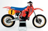
Use the pic of the frame you put up. If that's the type you have.
I think the pics lower down showing the other build is of another gen /type of frame?????? Buggered if I know.
Print it.
Get a RA set square, or better still, an adjustable one, Put it over the pic, starting at the rear cradle mount. With the picture showing the engine as it's situated there - (I Always strive to have the CS centre at the same height, or,if anything different, a mm or 2 lower, as the std donor engine. It's not hard to make a little centre pointer jig, to help you out on that if you have the original; engine, or can find a stocker of the bike in question) - it looks like a right angle bend would be damned close to giving you a straight shot of a full cradle going directly onto the downtube remnants, in that pic. and even allow you to leave the rad mount shown alone, You might be able to leave more of the downtube than what that frame had, by painstakingly removing the original Y at the weld to allow the cradle to go on lower. Even if the cradle is not absolutely in line with the angle of the DT, it Won't put flexing stress on the weld like that scary job shown in the other pictures.
When looking at that pic, you'd probably not need to 'straighten' the down tube, with either plating, a channel piece (U) or a 'cut to channel' square or rectangular section down from the downtube to the cradle, unlike the pic. with the scary 'beer belly' Y/downtube junction.
Card board is your friend. You can easily make templates of the cradle, dealing with the side view, and the forward view. This gives you something to look at, not imagine. You can easily produce the exact shape you want replicated by a tube bender, by making the cradle templates 3 dimensional, just with cardboard and sticky tape. Some measurements for defined points / limits, and you're good to go.
You, of course, need to make sure the angle of the top / front bend of the cradle allows you to fit the pipe in, radiators on etc, and you can get the engine in and out. For example, with that pic, it looks like you would be wise to shave of a bit of the rear of the downtube to allow lifting of the head etc. Boxing the end of the downtube is the go, or, put an arch under any plate at the front / rear of the downtube, cradle interface. The TM pic gives you a good idea of the shape example, and it can have the cut out of the downtube shape to allow it to fit flush on the cradle - or you can form the plate around any projecting downtube.
Taking pictures and printing them out, for assessment of ideas, estimations of angles and lengths, make it easier than just standing there and juggling things.
Sitting down with pics in front of you, then sitting down besides / in front of the bike / frame/engine, and just cogitating on the matter can make this so much easier. Making an AF, is pretty much at the level of a clever 7th grader, especially if you just think a little.
Hopefully this reads intelligibly, I had another operation on Thursday, and I'm still in nah nah land.
Go to it, Coley